28
ATtiny22/22L
The Stop condition provides a Timer Enable/Disable function. The CK down divided modes are scaled directly from the CK
oscillator clock. If the external pin modes are used for Timer/Counter0, transitions on PB2/(T0) will clock the counter even if
the pin is configured as an output. This feature can give the user SW control of the counting.
Timer Counter 0 - TCNT0
The Timer/Counter0 is realized as an up-counter with read and write access. If the Timer/Counter0 is written and a clock
source is present, the Timer/Counter0 continues counting in the timer clock cycle following the write operation.
Watchdog Timer
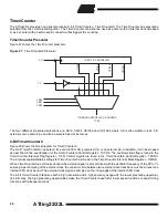
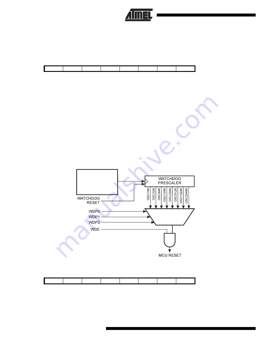
The Watchdog Timer is clocked from a separate on-chip oscillator. By controlling the Watchdog Timer prescaler, the
Watchdog reset interval can be adjusted as shown in Table 9. See characterization data for typical values at other V
CC
levels. The WDR - Watchdog Reset - instruction resets the Watchdog Timer. Eight different clock cycle periods can be
selected to determine the reset period. If the reset period expires without another Watchdog reset, the ATtiny22/L resets
and executes from the reset vector. For timing details on the Watchdog reset, refer to page 21.
To prevent unintentional disabling of the watchdog, a special turn-off sequence must be followed when the watchdog is
disabled. Refer to the description of the Watchdog Timer Control Register for details.
Figure 29. Watchdog Timer
Watchdog Timer Control Register - WDTCR
•
Bits 7..5 - Res: Reserved Bits
These bits are reserved bits in the ATtiny22/L and will always read as zero.
Bit
7
6
5
4
3
2
1
0
$32 ($52)
MSB
LSB
TCNT0
Read/Write
R/W
R/W
R/W
R/W
R/W
R/W
R/W
R/W
Initial value
0
0
0
0
0
0
0
0
Bit
7
6
5
4
3
2
1
0
$21 ($41)
-
-
-
WDTOE
WDE
WDP2
WDP1
WDP0
WDTCR
Read/Write
R
R
R
R/W
R/W
R/W
R/W
R/W
Initial value
0
0
0
0
0
0
0
0
1 MHz at V
CC
= 5V
350 kHz at V
CC
= 3V
Oscillator


