ATPL250A
PANCoordinator-EK Kit User Manual
USER GUIDE
Atmel-43106C-ATPL- PANCoordinator-EK Kit User Manual-UserGuide_06-Oct-16
Page 1: ...ATPL250A PANCoordinator EK Kit User Manual USER GUIDE Atmel 43106C ATPL PANCoordinator EK Kit User Manual UserGuide_06 Oct 16...
Page 2: ...h pitch 5 08 mm One erase jumper with pitch 2 54mm Features ATPL250A is a compact and high efficient device for a wide range of Smart Grid applications such as Smart Metering Smart Meters and Data Con...
Page 3: ...ion examples available based on G3 PLC Stack Atmel provides an Atmel G3 PLC PHY layer library which is used by the external MCU to take control of ATPL250A PHY layer device Three G3 PLC PHY layer exam...
Page 4: ...5 PLC Coupling 20 3 5 6 Peripherals 22 3 5 7 Interface Ports 23 4 ATPLCOUP007 Hardware 26 4 1 Overview 26 4 2 Features 26 4 3 Mechanical and user considerations 27 4 4 Hardware description 27 5 ATPLCO...
Page 5: ...pplication example 2 57 7 4 PLC application example 3 PHY Sniffer 61 7 4 1 ATPL Multiprotocol Sniffer tool Installation 62 7 4 2 Supplying the boards 64 7 4 3 USB connection 64 7 4 4 Programming the e...
Page 6: ...and Techniques Delivers Contextual Information About a Specific Topic Note to Quality and Performance Objectives to be Completed Actions to be Executed Out of the Target The Expected Result of an Ass...
Page 7: ...instruments Coupling boards kits are shipped in a protective anti static package The boards system must not be subjected to high electrostatic discharge We strongly recommend using a grounding strap...
Page 8: ...ly Requirements Parameter Condition Min Typ Max Unit TX Power Consumption FW PHY TX Test Console Application Low Impedance Load PRIME LISN Measured on VDD 16V DCDC output 3523 1 mW FW PHY TX Test Cons...
Page 9: ...reate your own account After that please contact with plc atmel com specifying your myAtmel user name your company name and email and request access to the specific evaluation kit you have acquired Pl...
Page 10: ...software documentation folder It contains some user guides as the description of the Atmel G3 firmware stack doc43081 Document describes in detail all layers from the Atmel G3 implementation as well a...
Page 11: ...sions between the two Atmel boards Please refer to chapter 7 2 for further information Take into account that the PANCoordinator EK provides one coupling board for CENELEC A band Figure 2 3 set over t...
Page 12: ...it User Manual USER GUIDE Atmel 43106C ATPL PANCoordinator EK Kit User Manual UserGuide_06 Oct 16 1 2 12 Figure 2 3 ATPLCOUP007 Coupling board Figure 2 4 ATPLCOUP002 Coupling board Figure 2 5 ATPLCOUP...
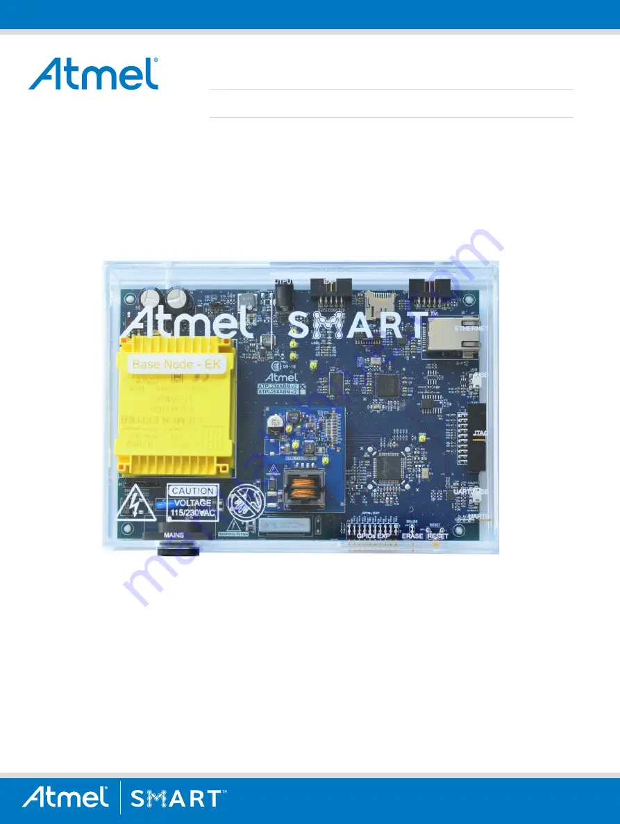
Page 13: ...C transceiver and on the SAME70 ARM Cortex M7 microcontroller ATPL250ABN PAN Coordinator board provides a platform to develop a complete communications system over G3 PLC technology Figure 3 1 ATPL250...
Page 14: ...ETM with instruction trace stream including Trace Port Interface Unit TPIU Memories 2048 Kbytes Embedded Flash 384 Kbytes Embedded SRAM Tightly Coupled Memory TCM interface with four configurations di...
Page 15: ...al UserGuide_06 Oct 16 1 5 15 High Speed USB 2 0 Device Xplained PRO Master Slave Interface UARTs over USB and CMOS levels Ethernet 10 100 Mbps Poly phase Base Node extension header Data Concentrator...
Page 16: ...is a CE mark product which passes EN60950 1 safety standard and EN50065 1 EN50065 2 3 EN50065 7 EMC and FCC as current carrier system standards It also satisfies Pb Free and ROHS directive ATPL250ABN...
Page 17: ...y include components such TFT displays The VDC voltage rail is used as input power of a high switching frequency buck converter U11 Figure A 2 to generate the regulated DC voltage VDD which is used to...
Page 18: ...tion is based on measuring the time difference between a specific PLC frame reception and the last zero crossing event of the mains single phase to which the device is connected Figure A 2 shows the z...
Page 19: ...by default as clock input by configuring the high frequency oscillator of ATSAME70Q21 in bypass mode This configuration allows reducing the overall BOM cost 12MHz crystal oscillator is not required w...
Page 20: ...received i e 50 60 Hz of the mains This is carried out by a high voltage capacitor C26 Figure A 8 Coupling stage could also voltage isolate the coupling circuitry from the external world by means of...
Page 21: ...eployments complying at the same time with the proper normative and standards The in band flat response filtering stage does not distort the injected signal reduces spurious emission to the limits set...
Page 22: ...rent packages U3 and U12 Figure A 4 are used in ATPL250ABN board to support the pinout of both the Adesto former Atmel family of DataFlash memories and standard serial flash products Since both packag...
Page 23: ...ses provided by Atmel for the base node reference design take this condition into account In addition to the complete reset of the PLC transceiver generated by an assertion of the PLL_INIT input the A...
Page 24: ...is connected to a CP2105 UART to USB 2 0 bridge to ease PC connectivity for debugging purposes The firmware projects provided by Atmel to ease the evaluation of the G3 PHY layer performance are based...
Page 25: ...erGuide_06 Oct 16 2 5 25 3 5 7 8 GPIOs Expansion Header The 2 54mm pitch right angle header J12 offers access to the I O ports of the microcontroller that are not used within the ATPL250ABN board Refe...
Page 26: ...s with a cost optimized performance transmission board in CENELEC A band for G3 PLC This board is set by default in the ATPL250ABN board of the PANCoordinator EK Figure 4 1 CENELEC bands 4 2 Features...
Page 27: ...9 5mm x 18mm LxWxH The operating temperature range is about 40 to 85 C 4 4 Hardware description Hardware files are contained in the Hardware folder Hardware HW_SCH PCB ATPLCOUP007v2 5 ATPLCOUP007 is a...
Page 28: ...rs with a full performance transmission board in ARIB bands This board is not set by default in the ATPL250ABN board of the PANCoordinator EK Figure 5 1 FCC and ARIB bands 5 2 Features The ATPLCOUP002...
Page 29: ...g temperature range is about 40 to 85 C 5 4 Hardware description Hardware files are contained in the Hardware folder Hardware HW_SCH PCB ATPLCOUP002v2 ATPLCOUP002v2 board is a PLC coupling driver boar...
Page 30: ...transmission board in FCC band This board is not set by default in the ATPL250ABN board of the PANCoordinator EK Figure 6 1 FCC and ARIB bands 6 2 Features The ATPLCOUP006v2 board includes the followi...
Page 31: ...H The operating temperature range is about 40 to 85 C 6 4 Hardware description Hardware files are contained in the Hardware folder Hardware HW_SCH PCB ATPLCOUP006v2 ATPLCOUP006v2 board is a PLC coupli...
Page 32: ...hat can be loaded into the microcontroller Kit projects are supported by IAR 7 70 Vision 5 14 or AS 6 2 versions or above From this point on it is assumed that a working copy of this IDE is installed...
Page 33: ...red JTAG emulator supporting Atmel ARM based microcontrollers Atmel SAM ICE is a JTAG emulator designed for Atmel SAMA5 SAM3 SAM4 SAM7 and SAM9 ARM core based microcontrollers including the Thumb mode...
Page 34: ...de UM08003 J Flash User Guide UM08004 RDI User Guide UM08005 GDB Server User Guide and UM08007 Flasher ARM User Guide Release notes for J Link DLL J Flash and J Link RDI DLL J Flash including sample p...
Page 35: ...aded for free ASF is an open source code library designed to be used for evaluation prototyping design and production phases The Atmel Software Framework is split in six main parts the avr32 directory...
Page 36: ...hesitate to visit our web site to get the last library updates 7 2 PLC application example 1 PHY Tester Board of the kit by default are programmed with the embedded PLC PHY Tester tool firmware for S...
Page 37: ...ART0 to communicate with the SAME70Q21 Load the firmware and run the application 7 2 1 Atmel PLC PHY Tester tool Installation To install Atmel PLC PHY Tester tool in a Windows Operating System execute...
Page 38: ...DE Atmel 43106C ATPL PANCoordinator EK Kit User Manual UserGuide_06 Oct 16 3 8 38 Select the users permissions and click Next Figure 7 6 Installation process slide 2 Click I Agree to continue Figure 7...
Page 39: ...sh Now the program is installed in your computer and a shortcut should have been created in your desktop Note that Atmel releases of G3 PLC versions lower than 1 2 2 run with PHY Tester PC Tool versio...
Page 40: ...tion about the USB device PAN Coordinator Evaluation Kit is provided with one micro USB cable in order to connect the user s host s PC s with the PAN Coordinator board Previous to connect the USB cabl...
Page 41: ...see section 7 1 5 and they depend on your operating system In order to program the firmware on the board set the JTAG probe SAM ICE on the JTAG connector J13 see section about JTAG programming mode 3...
Page 42: ...board is required i e ATPL250AMB Which it has been programmed with the respective application APPS_PHY_TESTER_TOOL See ATPL250A EK for more information PHY Tester Tool project of G3_va b c folder has...
Page 43: ...oncept In order to know if the boards were programmed successfully you can check if the green led LED0 D5 is blinking This indicates that the PHY Tester Tool application is running on SAME70Q21 device...
Page 44: ...RT0 If your COM port does not appear see section 7 2 3 press Find Ports button Select the BaudRate combo box of 115200 bauds Figure 7 17 Serial port selection Once COM port is selected click the Conne...
Page 45: ...enabled In case the tool cannot establish a communication with the board the tool shows the following error message Figure 7 19 Communication error Click the OK button and press Prev button to get ba...
Page 46: ...uct platform Model ID It is a 16 bit unsigned integer that identifies the model of the board Firmware ID It is a 32 bit unsigned integer that identifies the physical layer firmware running in the boar...
Page 47: ...ise button The user is also able to indicate the frequency where tonal noise is present and the firmware will configure the filters for this noise by means of Adapt to target frequency button Finally...
Page 48: ...nual USER GUIDE Atmel 43106C ATPL PANCoordinator EK Kit User Manual UserGuide_06 Oct 16 4 8 48 Figure 7 22 RX test parameters Default parameters are selected Click the Next button to continue Figure 7...
Page 49: ...receiver board has been configured the emitter board must be configured Launch another Atmel PLC PHY Tester tool and once the transmission board is supplied and USB cable connected configure the corr...
Page 50: ...ption selection Figure 7 26 Transmission Parameters tab The Transmission Parameters tab appears Figure 7 26 that allows you to configure the PLC coupling board plugged and the transmission parameters...
Page 51: ...X Power Allow to decrease the transmission power in steps of 3 dB Branch Configuration You can select the impedance branch transmission Preemphasis Allow to introduce an attenuation for each sub band...
Page 52: ...ended to check that all values correspond to the desired configuration before continue Figure 7 28 Configuration Summary tab To start the process click the Start Test button A new tab Test Executions...
Page 53: ...PANCoordinator EK Kit User Manual USER GUIDE Atmel 43106C ATPL PANCoordinator EK Kit User Manual UserGuide_06 Oct 16 5 3 53 Figure 7 29 Transmission test result...
Page 54: ...smis sion If an error occurs a descrip tive text will appear Modulation Scheme It indicates if modulation scheme is differential or coherent Modulation Scheme It indicates if modulation scheme is diff...
Page 55: ...e some frames The same TX RX processes could be done using another ATPL coupling board For that after power down the ATPL250ABN remove the ATPLCOUP007 board and set the new coupling board Take into ac...
Page 56: ...the host PC If PC doesn t recognize the USB download a USB driver from the USB cable manufacturer s web site Once the driver is downloaded unpack the driver archive to a folder on the host PC s hard...
Page 57: ...tx_test_console eww After that you can select the file conf_project h that it is located in the following project directory Software G3_va b c g3 workspace same70q21_atpl250abn_v2 thirdparty g3 phy at...
Page 58: ...Expansion connector J4 see Figure 3 2 Figure 7 33 COM Port selection Set 115200 in the Speed field In the Serial Category change the Flow Control to None The other fields should already be correctly...
Page 59: ...xample 3 Select data to transmit In this example we choose Random Data and 133 bytes This value 133 bytes is the maximum for Robust mode in CENELEC 4 Select TX tone map 0x3F in this example 5 Select T...
Page 60: ...transmission and press x to stop the process Default configuration is configured for ATPLCOUP007 coupling board for differential modulation scheme in Robust mode with 133 data bytes length and 5 4 mi...
Page 61: ...Sniffer In this example we present you the G3 PHY Sniffer project APPS_PHY_SNIFFER_TOOL G3 PHY Sniffer project is able to monitor data traffic on the G3 PLC network by means of an ATPL250ABN board and...
Page 62: ...on To install ATPL Multiprotocol Sniffer tool in a Windows Operating System execute the provided installer in the PCTools folder PCTools ATPL_Multiprotocol_Sniffer ATPL Multiprotocol Sniffer vX Y Z ex...
Page 63: ...EK Kit User Manual UserGuide_06 Oct 16 6 3 63 Figure 7 40 Installation process slide 2 Read and accept term and conditions expressed in the End User License Agreement Click I Agree to continue Figure...
Page 64: ...your destination folder Click Install to start the installation process Figure 7 43 Installation process slide 6 Click Finish Now the program is installed in your computer and a shortcut should have...
Page 65: ...the following Software folder Software G3_va b c g3 workspace same70q21_atpl250abn thirdparty g3 phy atpl250 apps ph y_sniffer_tool As we commented in a previous sections every coupling board is inte...
Page 66: ...this case G3 After that select the COM port and set the speed The default port is UART0 enhanced COM port and the speed for this application is 115200 bauds Also this tool is able to connect to a remo...
Page 67: ...n the menu Capture Start to begin logging data If tool establishes the communication with the COM port of the ATPL250ABN the status bar at the bottom of the window will show the current setup and stat...
Page 68: ...on technique OFDM can efficiently utilize limited bandwidth channels allowing the use of advanced channel coding techniques This combination facilitates a very robust communication over a power line c...
Page 69: ...components contents of thirdparty directory are showed in the following figure That is the way to integrate the whole platform in this structure ATPL250ABN SAME70 PLC G3 PLC and FreeRTOS Figure 7 50 S...
Page 70: ...any other RTOS The Atmel G3 stack is according to the following architecture PHY Layer PHY layer is in charge of frame transmission and reception this layer will be interrupt driven with events coming...
Page 71: ...Discovery and maintenance of the routes into the network IPv6 UDP and DLMS Layers These layers are generic and not directly related to G3 PLC protocol These layers will run each one on a separate OS t...
Page 72: ...refer to 7 2 2 in order to know how to supply the ATPL250ABN board 7 6 2 USB connection Please refer to 7 2 3 in order to know how to connect the micro USB cable with the ATPL250ABN board 7 6 3 Progra...
Page 73: ...to register 7 6 3 1 Setting EUI64 number Every device in a G3 network needs a unique EUI64 to be identified Every device in a G3 network needs a unique EUI64 to be identified Mechanism to store expec...
Page 74: ...n Figure 7 54 the boards are plugged into the same power line In this PLC example ATPL250ABN board is the PAN Coordinator and the other ones are the PAN Devices And users have to execute an instance o...
Page 75: ...d D5 LED0 are blinking to indicate the DLMS EMU application is running And red led D6 LED1 flashes when receives a PLC message Also when the PAN Coordinator and PAN Device send a PLC message the TX le...
Page 76: ...inal see Figure 7 57 Figure 7 57 Coordinator terminal window statics If the PAN Device is not an Atmel board only runs the bootstrap process due to DLMS emulation process will be ignored For more info...
Page 77: ...FCC Part 15 Subpart B 3 Narrowband OFDM PLC specifications for G3 PLC networks 2014 4 doc43079 ATPL250A Datasheet 2016 5 doc11296 SAME70 Series Datasheet 2016 6 doc43081 Atmel G3 PLC Firmware Stack U...
Page 78: ...de_06 Oct 16 7 8 78 Appendix A Board schemes A 1 ATPL250ABNv2 Schemes This section contains the schemes of the ATPL250ABN PAN Coordinator board Top level scheme Power supply scheme SAME70 Memory USB E...
Page 79: ...Manual UserGuide_06 Oct 16 7 9 79 Figure A 1 ATPL250ABN Top level scheme Figure A 2 ATPL250ABN Power supply scheme PAGE DESIGNATOR DEFAULT FUNCTION 2 J2 230Vac position 115 230Vac selection 2 J16 Ope...
Page 80: ...PANCoordinator EK Kit User Manual USER GUIDE Atmel 43106C ATPL PANCoordinator EK Kit User Manual UserGuide_06 Oct 16 8 0 80 Figure A 3 SAME70Q21 scheme Figure A 4 ATPL250ABN Memory scheme...
Page 81: ...PANCoordinator EK Kit User Manual USER GUIDE Atmel 43106C ATPL PANCoordinator EK Kit User Manual UserGuide_06 Oct 16 8 1 81 Figure A 5 ATPL250ABN USB scheme Figure A 6 ATPL250ABN Ethernet scheme...
Page 82: ...Coordinator EK Kit User Manual USER GUIDE Atmel 43106C ATPL PANCoordinator EK Kit User Manual UserGuide_06 Oct 16 8 2 82 Figure A 7 ATPL250A scheme Figure A 8 ATPL250ABN PLC Coupling transmission sche...
Page 83: ...ordinator EK Kit User Manual USER GUIDE Atmel 43106C ATPL PANCoordinator EK Kit User Manual UserGuide_06 Oct 16 8 3 83 Figure A 9 ATPL250ABN PLC Coupling reception scheme Figure A 10 ATPL250ABN Connec...
Page 84: ...it User Manual USER GUIDE Atmel 43106C ATPL PANCoordinator EK Kit User Manual UserGuide_06 Oct 16 8 4 84 Figure A 11 ATPL250ABN components location in top layer Figure A 12 ATPL250ABN components locat...
Page 85: ...Atmel 43106C ATPL PANCoordinator EK Kit User Manual UserGuide_06 Oct 16 8 5 85 A 2 ATPLCOUP007v2 5 schemes This section contains the schemes of the ATPLCOUP007 board PLC Coupling transmission scheme...
Page 86: ...r Manual USER GUIDE Atmel 43106C ATPL PANCoordinator EK Kit User Manual UserGuide_06 Oct 16 8 6 86 Figure A 13 ATPLCOUP007 PLC Coupling transmission scheme Figure A 14 ATPLCOUP007 components location...
Page 87: ...any warranties or indemnities The user assumes all responsibility and liability for handling and use of the evaluation board kit including without limitation the responsibility to take any and all ap...
Page 88: ...43106C ATPL PANCoordinator EK Kit User Manual UserGuide_06 Oct 16 8 8 88 Revision History Doc Rev Date Comments 43106C 10 2016 Minor changes 43106B 09 2016 Updating document according to EK contents...
Page 89: ...AG ES FOR LOSS AND PROFITS BUSINESS INTERRUPTION OR LOSS OF INFORMATION ARISING OUT OF THE USE OR INABILITY TO USE THIS DOCUMENT EVEN IF ATMEL HAS BEEN ADVISED OF THE POSSIBILITY OF SUCH DAMAGES Atmel...
Page 90: ...Mouser Electronics Authorized Distributor Click to View Pricing Inventory Delivery Lifecycle Information Microchip ATPANCOORDINATOR EK...