


AT-HDVS-200-TX-WP / AT-HDVS-200-TX-WP-BLK
10
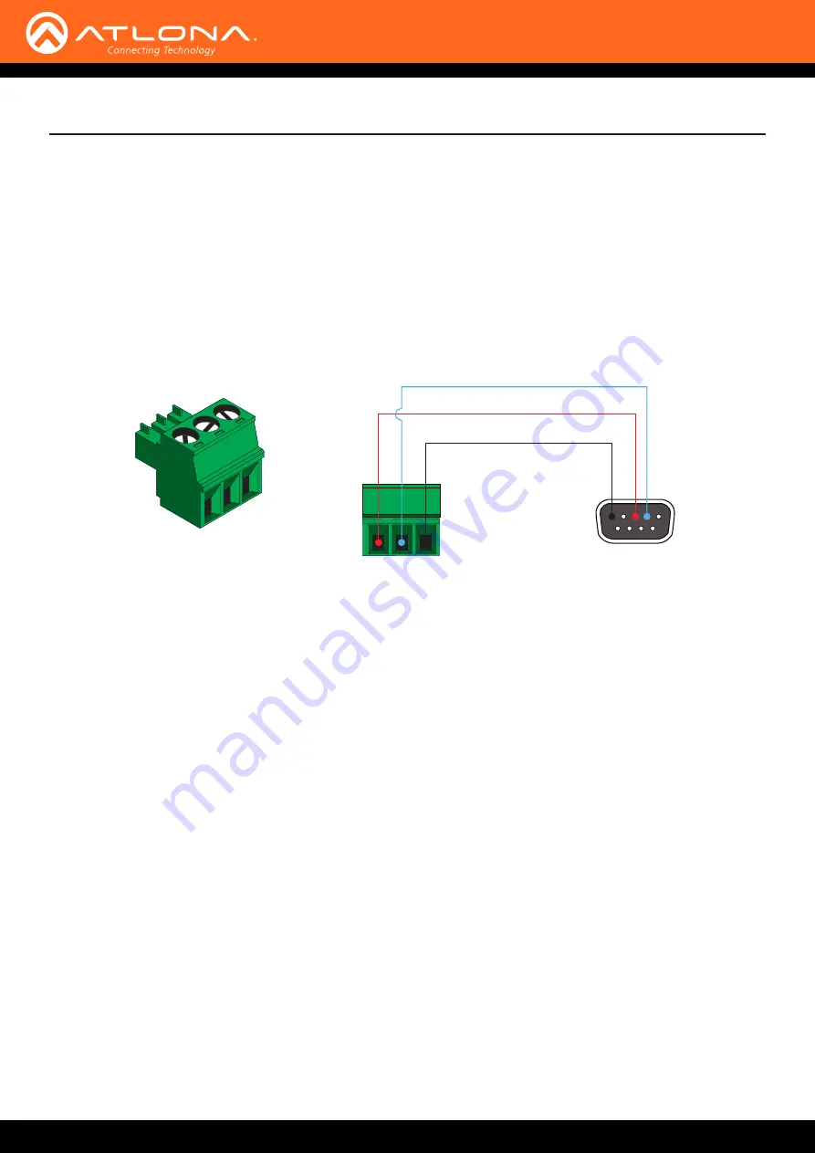
Installation
The AT-HDVS-200-TX-WP provides RS-232 control between an automation system and an RS-232 device. This step
is optional.
1.
Use wire strippers to remove a portion of the cable jacket.
2.
Remove at least 3/16” (5 mm) from the insulation of the RX, TX, and GND wires.
3.
Insert the TX, RX, and GND wires into correct terminal on the included Phoenix block. If using non-tinned
stranded wire, presss the orange tab, above the terminal, while inserting the exposed wire. Repeat this step for
the TX, RX, and GND connections.
RS-232 Connector
GND
RX
TX
1.
Determine the proper faceplate to be used for installation. If using the LAN port, then refer to
for information on changing the faceplate.
2.
Connect an Ethernet cable, up to 230 feet (70 meters), from the
HDBaseT
port on the switcher to
a PoE-compatible transmitter (not included). Ethernet cables should use EIA/TIA-568B termination.
CAT6a/7 solid core cables should be used for best results.
3.
Complete the installation of the AT-HDVS-200-TX-WP into the electrical box or mudring. Refer to the
if necessary.
4.
Connect an HDMI cable between the HD source and the
HDMI IN
port on the switcher.
5.
Connect a VGA cable from a VGA source to the
VGA IN
port on the switcher.
6.
Connect a 3.5 mm mini-stereo cable from the
AUDIO IN
port on the switcher to the analog audio source.
The AT-HDVS-200-TX-WP can pass audio either with or without a video signal. Refer to the
Audio Freerun
Status
option under the
7. OPTIONAL: Connect an RS-232 control device to the
RS-232
port on the switcher. This port is used to control
functions of the AT-HDVS-200-TX-WP, such as volume up/down, display on/off, etc.
No power supply is required for the AT-HDVS-200-TX-WP. This unit will be powered over the Ethernet cable,
from an HDBaseT receiver.
Connection Instructions


