background image

Atmosphere

User Manual

AtlasIED.com

TELEPHONE: (800) 876-3333

[email protected]

1601 JACK MCKAY BLVD. 

ENNIS, TEXAS 75119 U.S.A.

– 20 –


 •  

Target Window:

 When AGC output level is within the Target Window, AGC does not modify the gains. This is a sort of hysteresis  

control which helps AGC avoid being over-active once the general target gain has been reached. 15 dB is a good general setting for 
speech or music. Reduce the window to keep output levels closer to the target. Increase the window if AGC is causing noticeable 
“pumping” gain movements during normal operation.


• 

Max Boost/ Cut:

 These dictate how much gain the algorithm can boost/ cut as it attempts to maintain the required output level.


• 

Speed:

 How fast Auto-Gain adjusts gains to maintain the requested output level. 


 Note:

 A higher “Speed” is likely to produce the best results for voice while a slower “Speed” setting is best for background  

music applications. 

4.  AGC Input bar graph level with threshold setting and AGC Output level with target setting to manage settings range. 
5.  Bar graph meter displays the applied boost/ cut gain (dB) to keep signal in range in real time.

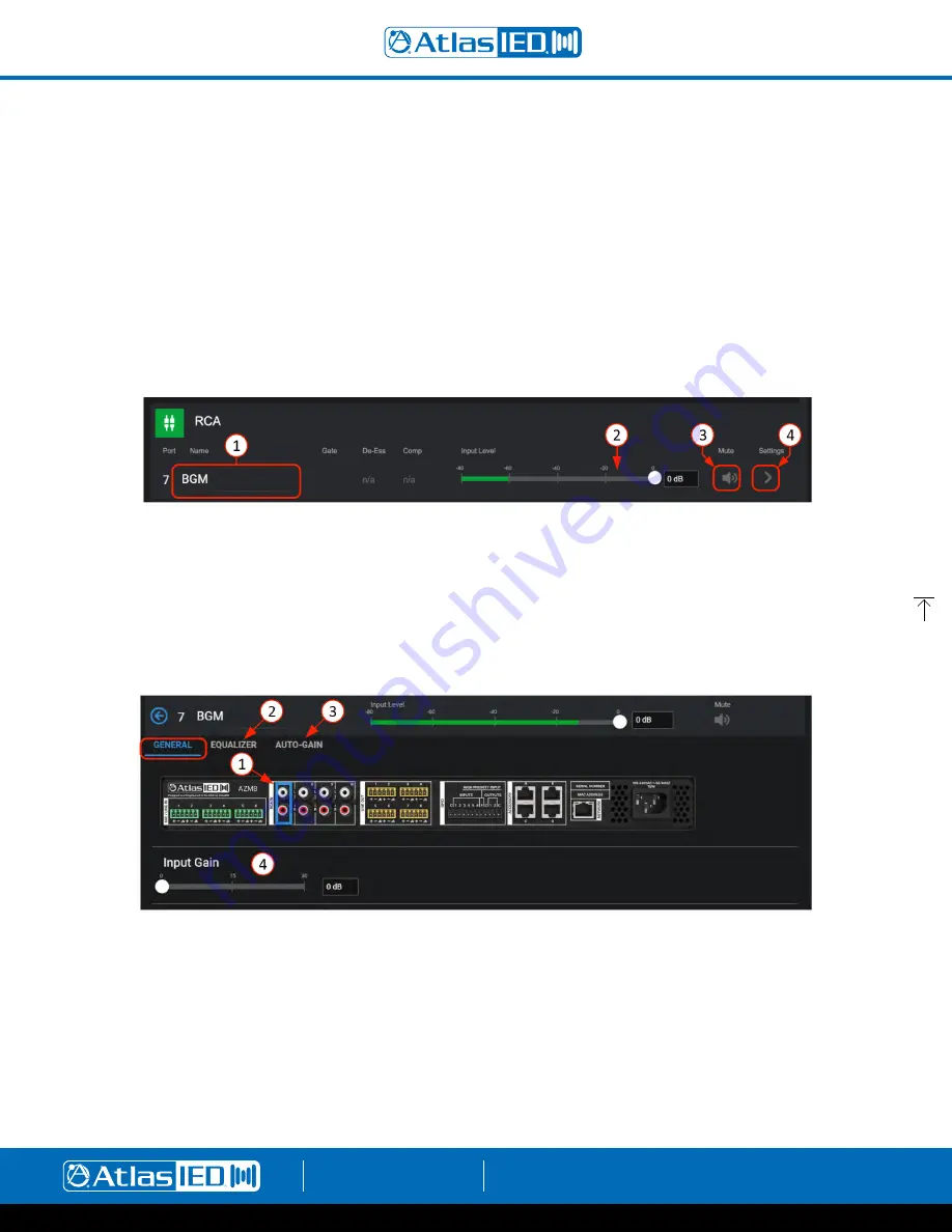
RCA Inputs

1.   Each input can be named here and will be added to the Inputs Selection list as well as populate all other respective inputs where displayed,  

system wide.

2.   Input Level adjust – move fader to desired level or type in dB level in window. When signal is present, fader animates as a pre-fader peak meter 

and shows: Green-signal activity, Red-clipping. 

3.  Mute – Select to toggle mute state.
4.  Opens RCA input General Settings page.

General Settings Page

1.  Displays rear panel and identifies physical location of input for wiring. 
2.  Equalizer – (same as Mic/Line Input EQ page above). 
3.  Auto-Gain Control – (same as Mic/Line Input AGC page above). 
4.  0 - 30dB of make-up gain available to fine tune input sensitivity. 

Summary of Contents for Atmosphere AZM4

Page 1: ...AtlasIED com TELEPHONE 800 876 3333 SUPPORT ATLASIED COM 1601 JACK MCKAY BLVD ENNIS TEXAS 75119 U S A Atmosphere Next Gen Expandable Zone DSP Controller User Manual ...

Page 2: ...tware Overview 13 Dashboard 13 Features 13 Inputs Page 14 Mic Line 14 General Settings Page 15 Gate 15 De Esser 16 Compressor 17 Equalizer 18 Auto Gain Control 19 RCA Inputs 20 General Settings Page 20 Audio Wall Plate Accessories 21 Audio Wall Plate Inputs 21 General Settings for A XLR Page 22 General Settings for A RCA Page 23 General Settings for A BT Page 24 How to Pair the A BT Wall Plate 24 ...

Page 3: ...Controllers 46 C ZSV General Settings 46 Zones Source and Volume Settings 47 Scenes 48 Messages 48 Screen Settings 49 Light Ring Settings 49 C V General Settings 50 Zones Volume 51 Light Ring 51 X ANS General Settings 52 Accessories Connection Rules 52 Scheduler 54 Steps to Create an Event 55 Diagrams 54 Connection Diagram 55 Block Diagram 55 Inputs and Outputs 55 Settings Page Overview 56 1 Confi...

Page 4: ...ité à l égouttement aux éclaboussures et ne posez pas des objets remplis de liquide sur l appareil WARNING If apparatus is equipped with Class I grounding plugs for safety purposes it must be connected to MAINS that employ a protective earth ground connection AVERTISSEMENT si l appareil est équipé de prises de terre classe I pour des raisons de sécurité il doit être branché sur un réseau ayant une...

Page 5: ...allation wiring time and complexity Configurable Mobile Device Control With the ability to turn any mobile device into a virtual App Less zone controller by simply scanning a QR Code with a phone or tablet Atmosphere mobile control is the easiest most cost effective way to provide zone control to the customer Setup the type of control you want on the user s device print QR codes directly from the ...

Page 6: ...Contents 1 6 2 7 3 8 4 9 5 10 AZM4 or AZM8 QTY 1 Quick Start Guide and Safety Sheet QTY 1 AZM4 1 2 Rack Adapter Screws Hardware Box QTY 1 AZM8 Rack Ears Screws Input Connector AZM4 QTY 4 AZM8 QTY 6 QR Code Placard QTY 1 GPIO Connector AZM4 QTY 1 12wy AZM8 QTY 1 12wy Output Connector AZM4 QTY 4 AZM8 QTY 6 IEC Power Cord QTY 1 AZM4 AZM8 ...

Page 7: ... hardware box and attach to each side To rack mount the AZM4 remove included rack ear and rack adapter and fasteners from hardware box and attach to each side Note The AZM4 is a RU device and can be mounted in a side by side configuration using the AtlasIED part PA702 RMK rack kit It can also be combined with the IP power strip AtlasIED AP S15HRIP Note When rack mounting the AZM the fan air flow i...

Page 8: ... to be configured within the UI before access is given Network See network status and settings change mode between access point WiFi ethernet change connection to available networks by signal strength enter SSID I O Signals Select Inputs or Outputs individually and see signal activity Accessories See Accessories connected to Ports A B AZM4 and A B C or D AZM8 select and read specific menu of Acces...

Page 9: ...udio Wall Plate Overload Too many Audio Wall Plates on a port Product Wall Plate Overload too many Wall Plates plugged into the AZM Backwards Audio Error Audio Wall Plate connected backwards Critical Temp Error Temperature exceeds maximum acceptable value AZM8 Back Panel AZM4 Back Panel 1 Balanced Mic Line Inputs Inputs 1 4 AZM4 and 1 6 AZM8 accept balanced input signals via the removable 3 5mm Ph...

Page 10: ...Time in 50ms increments a common C terminal for output ports 1 2 for external equipment interfacing 5 Accessory Ports RJ45 not Ethernet bus ports A B AZM4 or A B C D AZM8 are used for connecting Atmosphere Plug and Play accessories All accessories are recognized by the UI automatically when plugged in and can be assigned to any zone Multiple bus ports are provided to allow more accessories to be u...

Page 11: ...made RCA cables can be purchased from AtlasIED to simplify interconnection to external devices https www atlasied com volume controls cables audio cables unbalanced audio For RJ45 connections use CAT5e or CAT6 non shield network cable with T 568B or A wiring Pre made network cables must be pin to pin Do not use cross over network cables Always use best practices while terminating RJ45s to cables k...

Page 12: ...rom the AZM ethernet port to an existing network Logging in to the AZM 1 Open web browser on device that is on the same network as the AZM 2 Navigate to the IP address shown on the front panel of the AZM using the web browser address bar 3 Login using the username admin and password admin 4 After the first login follow the onscreen instructions to change the default log in credentials Method 2 WiF...

Page 13: ...ect to open To the far right there is a User link to settings page and an option for Full Screen view if desired The background has a dark or light Theme setting that can be selected when logging in or otherwise selected in settings under the Theme page 2 This area displays the project and user s name that is entered under the settings toolbar on the Project Settings page to the left On the right ...

Page 14: ... wired connections at the same time using two IP addresses Settings navigates to the Network Setup page 12 Upcoming Scheduled Events will be listed in this display The quick link navigates to the Event Scheduler page Inputs The Inputs page displays the five types of input sources available Mic Line Inputs RCA Inputs Audio Wall Plate Inputs Virtual Mix Inputs and a Signal Generator Input Mic Line I...

Page 15: ...nts 5 Dynamics active indicators show status of Gate De Esser and Compressor settings Gate 1 Gates sometimes referred to as Noise Gates are typically used to reduce noise from an open microphone when placed in a noisy environment by turning off or reducing the gain until the intended signal is present The signal must reach the threshold setting to open the Gate and allow the mic to be heard When t...

Page 16: ...bjective is to reduce the sibilance at the frequency where it is too loud 2 Enable the De Esser and Active indicator 3 Settings Frequency Hz Sensitivity Amount dB Hold Time ms Release Time ms Frequency the target frequency where the sibilance S sounds is most pronounced Sensitivity how much level at the target frequency is required to engage De Esser Amount amount of gain reduction applied after D...

Page 17: ...ettings Threshold Ratio Knee Attack Time Hold Time Release Time Makeup Gain Threshold The signal level required to engage the Compressor Ratio The amount of reduction compared to signal when compressing Knee The smoothing curve at the Threshold Attack Time The amount of time to fully engage the Compressor after signal level increases beyond the threshold Hold Time The amount of time Compression is...

Page 18: ...for each band 3 Enable Disable Filter by band and chose filter type selections Band 1 types include 1 PEQ 2 Low Shelf 3 High Shelf 4 Notch 5 High Pass Presets BW6 HP BW12 HP BW24 HP BW48 HP Band 2 3 types include 1 PEQ 2 Low Shelf 3 High Shelf 4 Notch Band 4 types include 1 PEQ 2 Low Shelf 3 High Shelf 4 Notch 5 Low Pass Presets BW6 LP BW12 LP BW24 LP BW48 LP 4 Dynamic fully adjustable bands on gr...

Page 19: ...ntain a consistent output level regardless of variations in input level This allows an integrator to set target input source levels for a room letting the Auto Gain maintain levels in target range so adjusting controls is not necessary 1 The input channel remains accessible for adjustment while using setup pages 2 Enable ON OFF bypass 3 Dynamic settings Threshold Target Level Target Window Max Boo...

Page 20: ...best results for voice while a slower Speed setting is best for background music applications 4 AGC Input bar graph level with threshold setting and AGC Output level with target setting to manage settings range 5 Bar graph meter displays the applied boost cut gain dB to keep signal in range in real time RCA Inputs 1 Each input can be named here and will be added to the Inputs Selection list as wel...

Page 21: ...at no audio wall plate accessories are connected to Port B Note It can take up to 30 seconds for an audio wall plate to be detected and start streaming audio 2 Once connected like Port A C D the Port will light up and allow naming which will be added to the Inputs Selection list and populate all other respective inputs where displayed system wide 3 This shows the dynamic processors activity indica...

Page 22: ... Connected Port ID includes port D and location 2 of the accessory on the port wiring bus 4 Dynamics Activity Indicators for DSP each light up if enabled and active 5 Mic Phantom Enable 6 Fixed High Pass Filter This is a separate EQ filter placed before the Equalizer page allowing roll off of low end before the Gate and Compressor allowing all bands of the Equalizer to be used for other requiremen...

Page 23: ...and Auto Gain definitions 2 Accessory Name displays reference to Port ID C3 and the editable name for this accessory 3 Connected Port ID C and location 3 of the accessory on the port wiring bus 4 3 5mm stereo summed shares RCA input and mixes RCA signal when plugged in 5 0dB to 20 dB of preamp gain available to fine tune input sensitivity for 10dB sources 6 This Locate push on push off button will...

Page 24: ...vice connection list 6 This Locate push on push off button will toggle the LED on the accessory to locate where it is installed Flashing will automatically stop after 30 minutes How to pair with the A BT Wall Plate 1 Using NFC Press the pairing button 1 and it will light blue a With the mobile device Bluetooth turned ON tap your mobile device to the NFC symbol 2 on the A BT b A BT indicator 1 will...

Page 25: ...al is present fader animates as a pre fader peak meter and shows Blue signal activity Red clipping 3 Mute select to mute input channel 4 This is the input settings link that navigates to the 4 channel Input Mix page Here the four source inputs from the inputs list can be named and selected Mix Level can bet set for each source and Master Mix Level can be set to create the Virtual sub mix Note Obse...

Page 26: ...e pink noise 2 Enter the frequency for sine waves in Hz 3 Set input level The Signal Generator can be assigned as a source on zone outputs only Zone Outputs The Outputs page displays the AZM4 or AZM8 4 or 8 zone outputs 1 Click on the Outputs toolbar to open the output zones page 2 Each output zone can be named here and will populate all other respective outputs where displayed system wide 3 Input...

Page 27: ...ut Source Selection and Priority Threshold when the selected priority input source s RMS levels exceed the priority threshold the priority source will duck the normal input source channels Note The ducker dynamic settings are common for all channels and are accessible via Settings Device Settings Priority Input Status Indicator will light yellow when the priority source is actively ducking the mai...

Page 28: ... 1 PEQ 2 Low Shelf 3 High Shelf 4 Notch 5 High Pass Presets BW6 HP BW12 HP BW24 HP BW48 HP Band 2 thru 5 Types include 1 PEQ 2 Low Shelf 3 High Shelf 4 Notch Band 6 Types include 1 PEQ 2 Low Shelf 3 High Shelf 4 Notch 5 Low Pass Presets BW6 LP BW12 LP BW24 LP BW48 LP 4 Select and set location and Q for bands 1 6 dynamically adjustable on graphic display 5 Select Presets to open a pop up with four ...

Page 29: ...has an Auto mode where the system learns the ideal compensation gain settings from user adjustments to the zone s output levels The Auto mode is very powerful and improves the all around audio in a changing room 1 Select to open the Ambient Noise Compensation settings page 2 Enable On bypass 3 ANC Parameters Slope How much dB gain to apply per dB change in noise level Attack Gain increase rate in ...

Page 30: ...ll Controller or C V C ZSV accessories After a few gain adjustments at the various ambient noise levels experi enced in the zone the system will be custom calibrated to react to the noise in a manner consistent with the end user s specific preferences 7 Reset Auto Mode Target This control resets the Auto Mode system to allow a fresh start for re training the algorithm Note It is recommended to use...

Page 31: ...Due to this complexity there is no single rule to define exact sensor placement However there are five basic rules that should always be considered when placing the X ANS Ambient Noise Sensor RULE 1 The distance between the sensor and the audience should be less than the distance between the sensor and the loudspeaker In most installations the sensor will be placed in the ceiling located in the zo...

Page 32: ...space Multiple X ANS sensors can be assigned to a single zone to help prevent over reaction to a noise source in one specific part of the zone Note The X ANS sensor is not a microphone and does not pick up audio and transmit it back to the system It converts levels to data and passes this level information back to the system Therefore there are no concerns that the system can violate any privacy R...

Page 33: ...paces the ambient level near the top of the high ceiling does not vary significantly enough to match the noise changes near the floor In this type of space a sensor located in the high ceiling may lose its effectiveness This problem is compounded when multiple zones are included in the same high ceiling area The ambient level is a culmination of the noise from all zones in the space Therefore it i...

Page 34: ...r starts limiting Knee controls the abruptness of the limiting as audio nears the threshold Attack Time how fast the limiter engages Hold Time how long it stays in limit mode after peaks drop below threshold Release Time how fast the limiter stops after hold time 4 This shows a signal output being limited to 26dB and the input signal is being reduced Gain Reduction slightly If the gain reduction i...

Page 35: ...or High Priority Input settings The message player activity is shown on the Dashboard when playing and in the upcoming events list when scheduled 1 Select Messages and NEW MESSAGE to create a new message settings profile or select an existing audio file to configure or modify its profile Note The same audio file can have multiple settings profiles saved as different names 2 Enter message name 3 Se...

Page 36: ...ht Local Preview player allows a selected message from the library to be previewed The audio will play on the default audio adapter on your device Priority Message priority allows you to assign the level of importance of your message list This is most important when two conflicting messages are triggered during the same time like an unexpected emergency event The highest priority plays first then ...

Page 37: ... faults can be selected to trigger Or they can be configured in Scenes to start a power sequencer projector and screen or start stop a third party voltage activated system device GPIO Inputs Setting Up a GPIO to Recall a Scene and or Play a Message In the UI select the GPIO Toolbar and the Inputs page opens 1 Enter a name for the function in one of 6 GPI ports 2 Select the type of activation contr...

Page 38: ...PIO Outputs 1 GPO 1 2 are either high or low voltage logic outputs only Note See Scenes GPO output settings Set High Set Low Toggle and Pulse adjustable in 50ms increments 2 Enter a name for the Function in one of 2 GPO ports 3 Select this to use system Faults to trigger the GPO for external devices When active Status will light ...

Page 39: ... Alerts will flash RED when active if selected 6 Select Action to Mute all Zones or Set all Zones to a source Page mic or in this example play a message on all Zones Select Repeat Message Indefinitely if desired 7 Select the previously named and saved message file 8 These faders allow setting the source level on the message input and zone outputs individually Note Default is 40dB 9 Enable sets por...

Page 40: ...nd rename save Note Exiting page saves settings 4 Enable the output zones to be included in the Scene 5 Select to apply source 6 Select audio source for each zone to include in the named Scene 7 Select to Apply Gain or leave unselected for an accessory like C V to adjust volume in the zone 8 Adjust desired Gain 9 Select to Apply Mute if desired for that Scene 10 Select to Include a saved message i...

Page 41: ...ccessories 1 C V Volume Control 2 C ZSV Volume Control with Source select scene recall and message playback 3 X ANS Ambient Noise Sensor for supplying ambient noise levels to the Ambient Noise Compensation algorithm 4 GEM Wall mountable frame placard to hold a virtual wall controller QR code printed from the user interface Controls for the QR code can be opted in the user interface The Accessories...

Page 42: ...ork as the AZM It is also recommended to use a static IP on the AZM to ensure repeated reliable connecting 5 Deletes virtual controller 6 Open the settings pages to configure the controller 7 Locate Icon will cause the connected device to flash to physically identify it 8 Front panel display QR code can be scanned and used as an additional virtual controller with the same access control as a C ZSV...

Page 43: ...Export Settings This saves the configuration file as a backup to use for importing 4 Various ways to use the QR codes copy link share link open in new window or print 5 Allows setting a four number PIN code to restrict access if desired Zones Sources Page 1 Add zones you want to control on the mobile device 2 Select the zones to be controlled by the mobile device 3 Select input Sources individuall...

Page 44: ...nes to be included to recall on mobile device 3 Set mute to allow it to be available on the mobile device to toggle Messages Page 1 Open Messages page 2 Select from the list of pre configured messages to be included on mobile device 3 Return to General Settings page and scan QR code with mobile device on the same network as the AZM Open the UI in mobile device Screen will show selections you made ...

Page 45: ...elect 4 Print QR Codes This will bring up a print window with all QR codes that have been configured Print and cutout the zone QR codes you would like to put in zones to be scanned 2 Mount in GEM holder and place on wall Additional GEM Holders can be purchased at https www atlasied com gem 5 3 Scan with mobile device and have instant control of the selections assigned Note Mobile device must be co...

Page 46: ...or this accessory 3 Connected port ID and location of the accessory on the port wiring bus 4 Import Settings this allows a saved configuration file to be imported to duplicate an existing setup 5 Export Settings This saves the configuration file as a backup or to use for importing to another C ZSV 6 This Locate click on click off button will toggle the LED on the accessory to locate where it is in...

Page 47: ...ones to be displayed for control by the mobile device 3 Select input sources individually or ALL to enable all sources to be displayed as a selection list on mobile device 4 Set an acceptable range of volume to adjust 5 Set Mute to allow it to be available on the mobile device to toggle 6 This Locate click on click off button will toggle the LED on the accessory to locate where it is installed Fla...

Page 48: ...vailable on mobile device 3 This Locate click on click off button will toggle the LED on the accessory to locate where it is installed Flashing will automatically stop after 30 minutes Messages Page 1 Select Messages tab to open 2 Select the Messages to be available to control playback from the mobile device 3 This Locate click on click off button will toggle the LED on the accessory to locate whe...

Page 49: ...oller 5 This Locate click on click off button will toggle the LED on the accessory to locate where it is installed Flashing will automatically stop after 30 minutes Light Ring Settings Page 1 Select Light Ring tab to open 2 Select to show and color of light ring for Meter level mode 3 Select to show and color of light ring for Fader level mode 4 Select to show and color of light ring for Mute Togg...

Page 50: ...rt wiring bus 4 Import Settings this allows a saved configuration file to be imported to duplicate an existing setup 5 Export Settings This saves the configuration file as a backup or to use for importing 6 This Locate click on click off button will toggle the LED on the accessory to locate where it is installed Flashing will automatically stop after 30 minutes 7 In addition to the wired wall cont...

Page 51: ...o allow it to be available on the C V or mobile device to toggle 5 This Locate click on click off button will toggle the LED on the accessory to locate where it is installed Flashing will automatically stop after 30 minutes Light Ring Settings Page 1 Select Light Ring tab to open 2 Select to show and color of light ring for Meter level mode 3 Select to show and color of light ring for Fader level ...

Page 52: ... shown in real time along with a button to unassign the sensor from the ANC and a jump button to the ANC settings page The ANC settings page also has a link on the sensor noise level meter that returns you to this page Plug and Play Accessories Connection Rules To guarantee good performance of all connected accessories follow these rules 1 Use CAT5e or CAT6 non shielded cable see cabling section t...

Page 53: ...Atmosphere User Manual AtlasIED com TELEPHONE 800 876 3333 SUPPORT ATLASIED COM 1601 JACK MCKAY BLVD ENNIS TEXAS 75119 U S A 53 Image 4 Image 5 Image 6 ...

Page 54: ...as an upcoming event The event log Settings Event Log will show scheduled events that have taken place to confirm it is working Steps to create an Event 1 When Add Event is clicked a page will open allowing configuration of the event profile 2 Name event 3 Select Color shows event as color on calendar and dashboard 4 Type of event action recall a Scene or play a message 5 Select recurrence type 6 ...

Page 55: ...rk and GPIO settings It can be printed as a system reference document for the project Block Diagram The Block Diagram inputs and outputs also show named I O allows editing and can be printed In addition the Block Diagram provides DSP settings page reference and navigation by clicking on any processing block area to go to the settings page for that processing block The blocks are in the order of si...

Page 56: ...d clone system configurations settings Import click on import and find the saved system configuration file azm on the pc where it was saved Select file and it will upload to the AZM Green check marks show files that will over write with uploaded settings Clone Exports green checked device settings for distribution Excludes Network Settings Error Log ANC Auto Mode User Accounts and Accessories Back...

Page 57: ... a network isn t available This is useful when setting up the device prior to being on site for install or if the site doesn t yet have an active connection Default setting is DHCP To set up Static IP enter the address subnet mask and default gateway then press UPDATE A popup message will verify you want to reboot to save configuration The IP address is displayed at the top of the front panel disp...

Page 58: ...ich will revert to DHCP The firmware version will remain unchanged Reset Users reverts user account settings back to default all other settings remain unchanged Reboot reboots the entire system including the accessories retaining the configuration set up 5 Clock There are three ways to set the clock select time zone region and automatic daylight savings adjustment 5a Manual select Date Time window...

Page 59: ...nses Software license agreements 8 User Account Manage registered user accounts The default login is admin admin After the first login follow the onscreen instructions to change the default password This will set up a user account User Account Setup After setting up the user account it can be modified using MODIFY USER There are three Role categories that determine access level Installer and Manag...

Page 60: ...EXAS 75119 U S A 60 9 Project Settings Name the project and make any specific notes associated with the Project Network or GPIO settings Note These notes will also populate the printable connection diagram notes 10 Theme Select Light Dark background theme Note This selection is also part of the initial log in ...

Page 61: ...Mode Static IP Subnet Mask Gateway Off Mode Change Mode Wifi Access Point Network Name IP Address Address Mode Static IP Subnet Mask Gateway Network List Wifi Networks Wifi AP Settings Scenes Messages Ethernet Wifi Inputs Outputs Input Signals List Output Signals List Port A Accessories Sensor Data Port B Port C Port D I O Temp CPU Temp PSU Temp System Clock Firmware Info Time Date NTP Version Las...

Page 62: ...mum Cable Size 18AWG Minimum Cable Size 24AWG RCA Right Channel Color Red Left Channel Color White Type Mono summed Pairs Sensitivity 10dBV Maximum Input 2 4 Vrms 7 6dBV 9 8dBu for Both Inputs Driven and 4 78 Vrms 13 6dBV 15 8dBu for a Single Input Audio Outputs Balanced Line Outputs Connector Type 3 5mm Pitch Euroblock Color Orange Maximum Output Level 20dBu 7 75 Vrms Maximum Cable Size 18AWG Min...

Page 63: ...AZM4 AZM8 Max 130 BTU Hr 256 BTU Hr No Accessories 75 BTU Hr 127 BTU Hr Front Panel Screen 128 x 128 Color TFT Normally White 1 45 Encoder 24 Detent Push Button Light Bar RGB Blue On Red Live Fault WiFi Type 802 11 b g n 2 4GHz Free Air Range 60ft Dimensions and Weight AZM4 AZM8 Rack Mount Requirements 1 RU 19 Dimensions with Rack Ears Unit W 19 x H 1 75 x D 11 7 483mm x 45mm x 297mm Dimensions Sh...

Page 64: ... Phantom Power Voltage 48VDC 10mA Accepts Unbalanced Inputs Yes Input Gain 0 60dB Maximum Voltage Input 2 dBu Input Impedance 3 4kΩ EIN 117dBu at 150Ω 20kHz BW CMRR Typically 50dB at 1kHz Indicator Green Signal Presence Red Clip Blue Locate Dimensions 1 78 x 4 2 x 2 1 Minimum Box Depth 2 25 A BT BT Standard V4 2 Audio Profile A2DP Open Air Range 100ft NFC Tap to Pair Indicator Green Paired Red Err...

Page 65: ...Atmosphere User Manual AtlasIED com TELEPHONE 800 876 3333 SUPPORT ATLASIED COM 1601 JACK MCKAY BLVD ENNIS TEXAS 75119 U S A 65 Dimensional Drawings 1 7 43 2mm 8 5 215 9mm 11 78 299 1mm AZM4 ...

Page 66: ...Atmosphere User Manual AtlasIED com TELEPHONE 800 876 3333 SUPPORT ATLASIED COM 1601 JACK MCKAY BLVD ENNIS TEXAS 75119 U S A 66 1 7 43 2mm 17 431 8mm 11 78 299 1mm Dimensional Drawings AZM8 ...

Page 67: ... 3333 SUPPORT ATLASIED COM 1601 JACK MCKAY BLVD ENNIS TEXAS 75119 U S A 67 Dimensional Drawings C V C ZSV A RCA A BT and X ANS share the same dimensions A XLR 4 5 114 3mm 2 75 69 9mm 2 06 52 4mm 1 71 43 4mm 4 5 114 3mm 2 75 69 9mm 1 86 47 2mm 1 15 29 1mm ...

Page 68: ...ipment complies with FCC radiation exposure limits set forth for an uncontrolled environment This equipment should be installed and operated with the following minimum distance between the radiator and your body AZM 4 AZM 8 6 5 cm 2 5 A BT 10mm 4 Canada AZM4 AZM8 Contains IC 20266 ATWILC1000 A BT Contains IC 7922A 3026 This device complies with Industry Canada license exempt RSS standard s Operati...

Page 69: ...ces comply with Part 15 of the FCC Rules Operation is subject to the following two conditions 1 this device may not cause harmful interference and 2 this device must accept any interference received including interference that may cause undesired operation This equipment has been tested and found to comply with the limits for a Class A digital device pursuant to part 15 of the FCC Rules These limi...

Page 70: ...T APPLICABLE LAW PREVENTS THE LIMITATION OF CONSEQUENTIAL DAMAGES FOR PERSONAL INJURY ATLASIED SHALL NOT BE LIABLE IN TORT OR CONTRACT FOR ANY DIRECT CONSEQUENTIAL OR INCIDENTAL LOSS OR DAMAGE ARISING OUT OF THE INSTALLATION USE OR INABILITY TO USE THE PRODUCTS THE ABOVE WARRANTY IS IN LIEU OF ALL OTHER WARRANTIES INCLUDING BUT NOT LIMITED TO WARRANTIES OF MERCHANTABILITY AND FITNESS FOR A PARTICU...

Reviews: