background image

ATLAS North America Proprietary

Sea Scan ARC Scout MKII Operations Manual

1 of 1

Page: 20

Issue: 1.2.4

SCTM2-OPS

Operations Manual

Sync Output Active High

5.1.4

Miscellaneous Settings

Time Synchronization Source

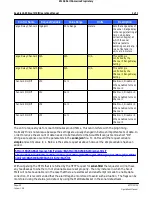
This setting controls the type of NMEA 0183 data string that the Scout MkII will synchronize its time with. 
Since there may be more than one timing sentence sent to the Scout MkII within the NMEA 0183 data
stream, it is required to synchronize to only one otherwise there may be issues with the Scout MkII's
timestamps jumping around due to timing of the incoming strings.  Choose from None, ZDA, AUV, and RMC.
 If None is set the Scout MkII can still be synchronized by using the SYNC string or by using the web
interface.  The default setting is ZDA.

Wake Up Source

The wake up source setting controls the means by which the Scout MkII wakes up from the sleep power
saving mode.  The 2 possible sources are Network (Wake On LAN - WOL) and SYNC In.  Please note that the
Sync In does not need to be enabled for the Sync Input to wake up the Scout MkII from sleep.  For more
information on the Scout MkII's sleep feature refer to the Sleep Power Management section of this manual.
 The default setting is Network.

Console Priority

This setting controls what information is displayed on the console.  Please see the Console Messages
section for more information.  The default setting is Normal.

Scout MkII Mode

This setting controls the unit's configuration state. The configuration setting is where the unit is configured
as a:

1. Single Frequency (standalone) unit, 

2. Dual Frequency Master, 

3. Dual Frequency Slave,

Note: Once, a unit is configured as a Slave Unit, the Network interface will only be available for
approximately 1 minuter after the Ethernet cable has been removed from the unit. 

Note: When a unit is configured as a Slave, all commands and settings are handled by the Master unit. 

This setting will be configured from the factory. 

5.2

Data Collection Control

Control of data collection is accomplished through HTTP requests for the

 sonar.html

 page or 

sonar.json

 file.

 The data collection parameters (URL encoded) are passed to the Scout MkII through the HTTP request URL. 
These parameters start after the "?' in the request URL (see example link below).   

Summary of Contents for Atlas North America Marine Sonic Technology Sea Scan ARC Scout MKII

Page 1: ...Sea Scan ARC Scout MKII Operations Manual V1 2 4 2017 Marine Sonic Technology ATLAS North America Doc SCTM2 OPS Marine Sonic Technology A Brand of ATLAS North America...

Page 2: ...693 9602 or visit our web site at http www marinesonic com This manual and the hardware software described in it are copyrighted with all rights reserved Under the copyright laws neither this manual...

Page 3: ...Configuration 16 Network Settings 17 Sonar Startup Settings 19 Sync I OSettings 20 MiscellaneousSettings 20 2 Data Collection Control 24 Range and Range Delay Settings 25 3 Commands 26 4 Status 30 5 F...

Page 4: ...Files 53 4 Creating Survey Files Section 8 Automatic Management 54 54 1 Power Management 54 Active Power Management 54 Sleep Power Management 55 Wake On LAN 56 Wake On Sync In 56 2 Temperature Managem...

Page 5: ...ATLAS North America Proprietary Sea Scan ARC Scout MKII Operations Manual 1 of 1 Page 4 Issue 1 2 4 SCTM2 OPS Operations Manual...

Page 6: ...ditional data such as Altitude Roll and Pitch 2 Quick Start Single Frequency Configuration This section serves as a how to for getting your Scout MkII setup and running quickly Follow the procedure be...

Page 7: ...Hz Chirp UP 256uS 150kHz 1 Transducer 900kHz Chirp UP 256uS 150kHz 2 Transducer 1800kHz Chirp UP 256uS 150kHz 3 Transducer 900kHz Chirp UP 256uS 150kHz Copyright 2016 Marine Sonic Technology Initializ...

Page 8: ...al Frequency Slave Damage to the device interface may occur if they are not properly configured 3 Quick Start Dual Frequency Configuration Note If the units are ordered in a dual frequency configurati...

Page 9: ...n a computer Ensure that the console is connected and that the terminal program on the PC is set to 115 2 kbps 8 data bits no parity and 1 stop bit Hand shaking should be turned off The console displa...

Page 10: ...Hardware Version 7 3 Board Rev PSU Logic RXTX 0 Transducer 1800kHz Chirp UP 256uS 150kHz 1 Transducer 900kHz Chirp UP 256uS 150kHz 2 Transducer 1800kHz Chirp UP 256uS 150kHz 3 Transducer 900kHz Chirp...

Page 11: ...e proper device configuration At a minimum the input power and network connections need to be connected 8 To verify proper operation connect the supplied serial connection to a serial port via DB9 to...

Page 12: ...zing network hardware done Initializing Sonar Hardware done Fri Jan 1 00 00 02 2016 PingRate 0Hz Temp 21 0C Power 12 0V 0 500A 6 0W SDS 0 packets 0KB 0 FIFO Network Using IP 169 254 86 213 Subnet 255...

Page 13: ...ay occur if they are not properly configured 12 Check that everything is connected according to the Sea Scan ARC Scout MkII Installation Guide following the dual frequency installation instructions At...

Page 14: ...6 Marine Sonic Technology Initializing network hardware done Initializing Sonar Hardware done Fri Jan 1 00 00 02 2016 PingRate 0Hz Temp 21 0C Power 12 0V 0 500A 6 0W SDS 0 packets 0KB 0 FIFO Network U...

Page 15: ...ver Web Interface used for control and configuration 2 TCP Console used for NMEA Data input and Console Commands available on TCP or RS 232 3 SDS Data Output available on UDP only Below is a list of t...

Page 16: ...tware version firmware version build date electronic board versions Transducer Configuration Application Settings app_settings html Shows the system s application settings Allows the user to edit the...

Page 17: ...button will submit the settings shown on the page to the Scout MkII The Scout MkII will then store the settings The Scout MkII will then display a new page with the new settings Clicking the Reset but...

Page 18: ...els 0 and 1 In the single frequency 2 channel configuration the range is controlled by channel 0 Range Delay This setting controls the initial range delay Range delay sets the range starting at time 0...

Page 19: ...to columns The channels are labeled Master 0 1 Note The Single Frequency system utilizes Channels 0 and 1 Channel Enabled This settings enables or disables the channel Channel Bandwidth The bandwidth...

Page 20: ...Sync Output is enabled the Scout MkII will send out a TTL compatible synchronization pulse on its Sync Out pin The pulse shape is determined by the pulse length and pulse decimation settings The defau...

Page 21: ...nput to wake up the Scout MkII from sleep For more information on the Scout MkII s sleep feature refer to the Sleep Power Management section of this manual The default setting is Network Console Prior...

Page 22: ...h1 1 ch2 1 ch3 1 Note In the Dual Frequency configuration Range and Range delay are controlled by Channels 0 and 1 Channel 2 Channel 0 Channel 3 Channel 1 Sending the range and or range delay message...

Page 23: ...r 1 Enable 1 Disable 0 When enabled locks the range selection to match Channel 0 s range setting Range Channel 0 rngm0 1 0 to 300 0 meters Sets the slant range of the sonar Range Channel 1 rngm1 1 0 t...

Page 24: ...l takes around 50ms This can interfere with the ping timing Normally this is not an issue because the settings are usually changed in between important sets of data In order to reduce the amount of da...

Page 25: ...1 ch3 0 or 1 5 2 1 Range and Range Delay Settings In order to make the best use of the differing frequency maximum ranges while still maintaining the best possible image the ARC Scout MkII allows the...

Page 26: ...lay for all channels based on the settings for channel 0 Settings Collection Enabled Yes Transmit Enabled Yes Range Lock Yes Range Delay Lock Yes High Frequency Range 30m High Frequency Range Delay 5m...

Page 27: ...el0 onoff 1 bw 150 dcycle 26 rng 30 0 rngdly 0 0 channel1 onoff 1 bw 150 dcycle 13 rng 30 0 rngdly 0 0 channel2 onoff 1 bw 150 dcycle 26 rng 30 0 rngdly 0 0 channel3 onoff 1 bw 150 dcycle 13 rng 30 0...

Page 28: ...0 0 to 30 0 Indicates the current duty cycle of the channel Maximum is 30 0 30 0 Channel 1 s Range Setting rng meters 0 0 to 300 0 Indicates the channel s range setting 30 0 Channel 1 s Range Delay Se...

Page 29: ...Range Delay Setting rngdly meters 0 0 to 300 0 Indicates the channel s range delay setting 0 0 Master Unit s Status Master N A N A N A N A Master Unit s Temperature temp Degrees Celsius 0 0 to 100 0...

Page 30: ...ve Unit s Temperature temp Degrees Celsius 0 0 to 100 0 Indicates the Slave unit s current temperature 27 00 Slave Unit s Voltage In vin VDC 0 0 to 99 9 Indicates the Slave unit s current input voltag...

Page 31: ...ond It uses Javascripts XMLHttpRequest object to do the heavy lifting Upon receipt of the status json data the Javascript code uses the JSON object to parse the JSON data into a Javascript object that...

Page 32: ...ame Click the Upload button to validate the firmware file After a brief delay of about 30 seconds or less the Scout MkII should indicate the correct file and that the file was successfully validated A...

Page 33: ...web page hosted by the Scout MkII The request uses the time parameter The time is encoded as the number of decimal seconds since the EPOCH January 1st 1970 This time down to 1 second resolution is com...

Page 34: ...ork connected Useful for troubleshooting TCP Port 23 Telnet up to 2 connections available UDP Port 10001 Connectionless This is a receive only interface however the Scout MkII can receive packets from...

Page 35: ...guration issues Network Information netinfo Prints out the network configuration information to the console System Reset reset Performs a soft reset of the Scout MkII system Shuts down all functions f...

Page 36: ...nations are RMC AUV GGA and VTG GLL and VTG In addition to the above navigation data string combinations one of the sentences containing water depth and or altitude is desirable As with the navigation...

Page 37: ...61229 487 hhmmss ss h hour m minutes s seconds Status A A valid data or V invalid data Latitude 3723 2475 ddmm mmmm d degrees m minutes N S Indicator N N North or S South Longitude 12158 3416 dddmm mm...

Page 38: ...d degrees m minutes E W Indicator W E East or W West Position Fix Indicator 1 0 Invalid 1 GPS Mode Valid 2 DGPS Mode Valid 6 Dead Reckoning Valid Satellites Used 07 HDOP 1 0 Horizontal Dilution Of Pre...

Page 39: ...contains Course Over Ground and Speed Over Ground Example GPVTG 309 62 T M 0 13 N 0 2 K A 23 Format Description Name Example Units Description Start Of String indicates start of string Message ID GPVT...

Page 40: ...elimeter The checksum comes after this character 64 2 Digit Hexadecimal Sentence Terminator CR LF Indicates end of sentence 6 3 1 6 ZDA This string contains the current UTC time It is usually associat...

Page 41: ...now becomes the Altitude distance from the sonar to the sea floor Adding the values together will result in Total Water Depth distance from the surface to the sea floor Below is an example of this str...

Page 42: ...es m minutes up to 6 decimal places N S Indicator N S N North or S South Longitude longitude Longitude in the format dddmm mmmm d degrees m minutes up to 6 decimal places E W Indicator E W E East or W...

Page 43: ...e Terminator CR LF Indicates end of sentence 6 3 2 4 SYNC The SYNC string allows the host computer to set the Scout MkII s real time clock The Embedded system starts up with the time of January 1st 19...

Page 44: ...0A value an ASCII Line Feed character For more information please see the National Marine Electronics Association 0183 standard 7 SDS Data Output The SDS Sonar Data Stream was created to be flexible...

Page 45: ...are used in the SDS H header file as well as in the following section s are listed below Type Size in Bytes Signed Unsigned BYTE 1 unsigned WORD 2 unsigned DWORD 4 unsigned int 4 signed short int 2 s...

Page 46: ...e of mechanisms to insure the stream has valid data The first method which is mentioned above is to read only the tags that your software understands Another mechanism is the 8 bit checksum of the pac...

Page 47: ...s To learn more about how to synchronize the data stream please refer to Synchronizing the Data Stream later in this section The Sync data packet uses the miscellaneous bytes in the packet header The...

Page 48: ...The SDS_DATA_SONAR_PING_CHANNEL structure is as follows Element Variable Type Description wSonarType WORD Stores the type of sonar used to the collect the data Typically Port Starboard Port2 Starboard...

Page 49: ...tures end The number of samples in each channel is dictated by the wSamples field for that particular channel The start of the samples are calculated using the byChannelCount field in the Ping structu...

Page 50: ...he Scout MkII sets this to DATASOURCE_SONAR dLatitude double The latitude encoded as decimal degrees dLongitude double The longitude encoded as decimal degrees fCOG float The course over ground in deg...

Page 51: ...OURCE_SONAR fDepth float This is the depth in meters fAltitude float This is the altitude in meters 7 1 3 6 NMEA Data Packet The NMEA data packet stores a NMEA string the length of the string includin...

Page 52: ...ld contains the Scout MkII s alarm flags The MkII data packet stores information specific to each channel in a MkII_CHANNEL data structure as described below There are 4 individual channel structures...

Page 53: ...header is valid Then read the reference time stamp to get the exact date and time of this packet as well as when to expect the next SYNC packet 7 2 SDS Over UDP Streaming SDS data over UDP IP is stra...

Page 54: ...sion xvy short for Xml surVeY The Survey File must be in the same folder as the sds data files The following example can be used with the sds files and file prefix changed to what has been used during...

Page 55: ...ey will create any missing xml files needed However an example blank marker xml file is shown below xml version 1 0 encoding ISO 8859 1 MarkerList NextID 0 id 0 8 Automatic Management The Scout MkII h...

Page 56: ...i p Level Power Consumption Wake Up Time Notes Idle on but not collecting data 6 3W 0 Seconds None Sleep Wake On LAN 4 7W 1 Second Wakes up when the WOL Magic Packet is received Sleep Sync In 2 7W 3 S...

Page 57: ...s serial number goes by the following format AAAAAA BB CCCC where A Model Number B Frequency Designation and C Unit Number Below is a C code snippet used for encoding the MAC address Form the MAC addr...

Page 58: ...nd typically are sent by the host system several times per second therefore these sentences can be configured to set the system time in the Scout MkII s Application Settings The SYNC command s sole pu...

Page 59: ...therefore power consumption The act of transmitting also results in increased transducer temperature While the Scout MkII does not have the ability to sense the temperature of the transducers it does...

Page 60: ...oise range for a delivered system during bench testing is 20 30 counts To determine the amount of EMI and Noise Interference the system is receiving while installed in the platform perform the followi...

Page 61: ...system into the host platform 13 Configure the Scout MkII as per Step 5 14 The Host Platform sensors should be powered and if possible operating as if they were on a standard mission 15 If the units...

Page 62: ...nar 5 If possible move noise inducing systems and or verify system grounds throughout the vehicle to improve EMI Noise Interference 6 If possible provide extra external shielding to the Scout MkII ele...

Page 63: ...rformance and in some cases render that affected channel s picture unreadable An elevated noise level can be determined by reading the average and minimum values on the Signal Statistics Window in Sea...

Page 64: ...Transducers by swapping the connection points on the electronic s module s a If the problem does not follow the cabling and transducer then the issue is within the electronic s module itself Please co...

Page 65: ...th the Transducers 4 Using a hydrophone connected to an Oscilloscope and verify that the transducer is transmitting 5 If a hydrophone is not available an audible transmission envelope can be heard wit...

Page 66: ...ic Transducer Acoustic Specification Frequency 300 kHz 600 kHz 900 kHz 1200 kHz 1800 kHz Operating Range maximum per side 250 meters 140 meters 80 meters 45 meters 25 meters Along Track Resolution End...

Page 67: ...55 45 0 46 08 36 33 33 08 31 45 50 0 49 04 39 28 36 03 80 0 66 75 57 00 53 75 100 0 78 56 68 81 140 0 102 19 92 43 150 0 108 09 200 0 137 62 250 0 167 15 300 0 196 67 12 2 Power Specifications Power S...

Page 68: ...ransmit 5VDC Absolute Maximum Rating VDD Supply Voltage 5 5 VDC Input Voltage VDD 0 5 VDC VSS 0 5 VDC Output Voltage VDD 0 5 VDC VSS 0 5 VDC Output Current 10mA Power Monitoring and Protection Conditi...

Page 69: ...0 Updates concerning SW changes Power consumption changes February 2017 1 2 4 Updates for configuring different ranges per frequency Updates concerning SW changes August 2017 14 Contact and Support In...

Reviews:

Related manuals for Atlas North America Marine Sonic Technology Sea Scan ARC Scout MKII