


- 22 -
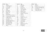
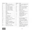
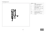
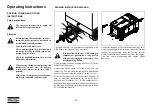
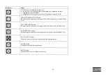
Reference
Name
C1
Spare I/O (female contacts)
C2
CAT engine service tool connector
F1
Fuse 10A, main
F2
Circuit breaker 10A, Engine
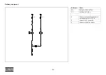
F3
Circuit breaker 10A, Engine
F4
Circuit breaker 10A, Engine
F5
Circuit breaker 10A, Engine
F13
Circuit breaker 60A, Alternator
G1
Battery
G2
Battery
G3
Alternator
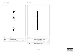
H4
Warning flasher light
H6
Horn
K0
Relay, Starter motor
K1
Relay, Aux. starter
LS1
Level Switch, Coolant level
Shutdown
LS2
Level Switch, Coolant level Warning
LT1
Level sensor, Fuel level
M1
Starter motor
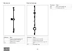
N1
Compressor Control Module
N2
Engine Control Module (Caterpillar)
N7
Compressor control module remote
connector
PS1
Pressure Switch, Airfilter
PT1
Pressure sensor, Vessel pressure
Reference
Name
PT2
Pressure sensor, Regulating Pressure
PT3
Pressure sensor, Oil stop valve
pressure
PT4
Pressure sensor, Interstage pressure
R2
Resistor, 120 Ohm CAN J1939
R3
Resistor, 120 Ohm CAN J1939
S1
Emergency Stop
S4
Battery switch
X9
Option box connector
TT1
Temperature sensor, PT1000, LP
Element temperature
TT2
Temperature sensor, PT1000, HP
element temperature
TT3
Temperature sensor, PT1000,
Ambient temperature
Y1
Loading Valve
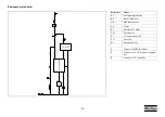
1
24 VDC (power supply box) for
Spare I/O’s and options
2
Fused 24 VDC after Emergency
Stop for Spare I/O’s and options
3
Fused 24 VDC for Spare I/O’s and
options
4
Power After Contact for Spare I/O’s
and options
5
5 VDC for Spare I/O’s and options
6
Ground for Spare I/O’s and options
7
Ground (power supply box) for
Spare I/O’s and options
Summary of Contents for XRHS 1150 CD4 C3 WUX
Page 2: ......
Page 16: ... 16 Main parts ...
Page 18: ... 18 REGULATING SYSTEM ...
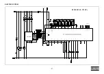
Page 21: ... 21 ELECTRIC SYSTEM 9822 0963 40 C13 HP ...
Page 105: ......
Page 106: ...www atlascopco com ...