Technical Manual & Parts Lists
30
Side Sealing Bars
WARNING:
Wait until the heat sealing bar has cooled enough (approx. 3 hours) before servicing seal
bars or the areas near the bars. If maintenance on the machine is absolutely necessary before sealing bars
have had a chance to cool down, the person performing the maintenance must use safety equipment
approved by OSHA or local law to protect against burns.
Refer to table on page 29 for details
(A). - Welding is even and the depth of a weld's right
.
The melted plastic appears with small bubbles and a connecting line between these bubbles. The weld is
constant throughout.
(B). - Sealing bars are too deep
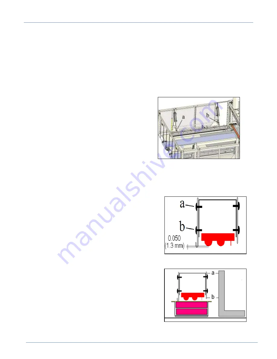
To set the depth of the shaft, loosen the nuts (a), (b) and
rotate the cylinder shaft clockwise from top view on both
cylinders which support the seal bars. Rotate the shaft ¼
turn at a time, and test the quality of the seal between each
setting.
(C). - Heat sealing bars Lack depth.
Adjust the height of the shaft, loosen the nuts (a), (b) and
rotate cylinder shaft counterclockwise from top view on
both cylinders which support the seal bars. Rotate the shaft
¼
turn at a time, and test the quality of the seal between each
setting.
(D). - Heat sealing bar is not parallel with the non-stick tape lengthwise.
Adjust the parallelism between the heat seal bar and nonstick ribbon by loosening the nut (a) or (b) and
rotate the corresponding cylinder rod. Rotate the shaft ¼ turn at a time, and test the quality of the seal
between each setting.
(E). - Irregularity along the sealing
1. Make sure the sheet metal clamping the plastic film is at
the correct height. The bar should be protruding to 0.050 inch
(1.3mm) below the seal bars. To do this, loosen the screws (a)
and (b) holding the pressure plate and lower it until the
measurement is correct. Atlanta Attachment has a tool to
facilitate this adjustment Part # 1390965 included in the kit of
replacement parts.
2. Verify that the sealing bar is parallel with reference to the
non-stick tape. Rest the cooled seal bar on the non-stick tape
and place a square on the table top next to seal bar and check
the distance between the top of the heat baffle (a) and the
bottom (b). You should have equal reference to the square.
Make sure that the sheet metal is on the rubber and not the
metal lip of the bottom tray. You should have equal reference
to the square. If not, go to alignment on page 31.
Note:
Upper bar should always come into contact with tape and silicone cushion. At no time should any part of
the upper seal bar contact the metal of the lower bar assembly.
Summary of Contents for 1390BX
Page 2: ......
Page 43: ...Technical Manual Parts Lists 35 Example B Good seal Good seal Lack depth ...
Page 56: ...Technical Manual Parts Lists 48 ...
Page 67: ...Technical Manual Parts Lists 59 ...
Page 68: ...Technical Manual Parts Lists 60 ...
Page 70: ...Technical Manual Parts Lists 62 ...
Page 72: ...Technical Manual Parts Lists 64 ...
Page 92: ...Technical Manual Parts Lists 84 ...
Page 94: ...Technical Manual Parts Lists 86 ...
Page 102: ...Technical Manual Parts Lists 94 ...
Page 112: ...Technical Manual Parts Lists 104 ...
Page 114: ...Technical Manual Parts Lists 106 ...
Page 124: ...Technical Manual Parts Lists 116 1391104 Valve Bank Assembly AAC Drawing Number 1391104 Rev 3 ...
Page 126: ...Technical Manual Parts Lists 118 ...
Page 134: ...Technical Manual Parts Lists 126 ...
Page 136: ...Technical Manual Parts Lists 128 ...
Page 137: ...Technical Manual Parts Lists 129 1391106 Roll Loading Kit AAC Drawing Number 1391106 Rev 4 ...
Page 138: ...Technical Manual Parts Lists 130 ...
Page 139: ...Technical Manual Parts Lists 131 ...
Page 140: ...Technical Manual Parts Lists 132 ...
Page 142: ...Technical Manual Parts Lists 134 ...
Page 144: ...Technical Manual Parts Lists 136 ...
Page 146: ...Technical Manual Parts Lists 138 ...
Page 148: ...Technical Manual Parts Lists 140 ...
Page 150: ...Technical Manual Parts Lists 142 ...
Page 154: ...Technical Manual Parts Lists 146 ...
Page 157: ...Technical Manual Parts Lists 149 1391162 Cable kit 125688B ...
Page 158: ...Technical Manual Parts Lists 150 1391874 Cable Kit ...
Page 159: ...Technical Manual Parts Lists 151 1390B PD Pneumatic Diagram 125373D ...
Page 160: ...Technical Manual Parts Lists 152 1390B PD2 Pneumatic Diagram optional equipment 125694B ...
Page 161: ...Technical Manual Parts Lists 153 1390BX PD Pneumatic Diagram 125894C ...
Page 162: ...Technical Manual Parts Lists 154 1391450 PD Pneumatic Diagram Pusher Optional 125892C ...
Page 163: ...Technical Manual Parts Lists 155 1390 PD3 Pneumatic Diagram Full Compression 125630B ...
Page 164: ...Technical Manual Parts Lists 156 1390 PD4 Pneumatic Diagram Full Compression 125631B ...
Page 165: ...Technical Manual Parts Lists 157 1390B WD1 Control Box Wiring Diagram 125493B ...
Page 166: ...Technical Manual Parts Lists 158 1390B WD2 Wiring Diagram SBUS 125494B ...
Page 167: ...Technical Manual Parts Lists 159 1390BX WD Control Box Wiring Diagram 125845C ...
Page 168: ...Technical Manual Parts Lists 160 1390BX WD2 Wiring Diagram SBUS 125893C ...
Page 169: ...Technical Manual Parts Lists 161 ...


