Manual, Robotic Electric Tool Changer, QC‑18
Document #9620‑20‑B‑18 Electric Tool Changer‑06
Pinnacle Park • 1031 Goodworth Drive • Apex, NC 27539 • Tel: 919.772.0115 • Fax: 919.772.8259 •
B-8
US Patent No.: 8,132,816 B2
2.2 Master Plate Installation
Tools required: 4 mm hex key, torque wrench
Supplies required: Clean rag
1. Make sure mounting surface of the Master plate and robot arm or interface plate are clean and
free of debris.
2. If an interface plate is required, attach the plate to the robot using appropriate mounting fasteners
and torque values.
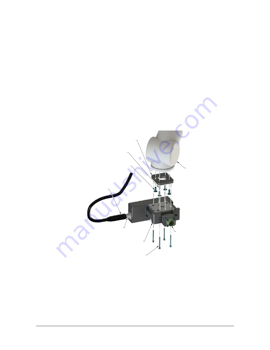
3. Attach the Master plate assembly to the interface plate using the (4) M4 socket head cap screws
provided. Tighten to 15 in‑lbs (1.7 Nm).
4. Connect and route the cable and secure per customer cable routing requirements.
5. Connect controller to customer interface cable to the 12‑pin connector on the QC‑18 servo motor module
and connect cable to customer interface as prescribed in
Section 2.8—Electrical Connections
6. Connect any electrical connection to optional modules.
7. If installation is complete, the Master plate may be put into normal operations.
Figure 2.1—Typical Master Plate Installation
Robot
ATI or Customer Supplied
Interface Plate (If Required)
Customer Supplied
Mounting Fasteners
Customer Supplied
Controller Cable
Availabe from ATI
(4) M4 Socket
Head Cap Screws
Electrical
Connection
QC-18 Master Assembly
(9120-018M-2387 Shown)
12-Pin Connector
Customer Supplied
4 mm Dowel Pins
2.3 Master Plate Removal
Tools required: 4 mm hex key
1. Place the Tool in a secure location.
2. Uncouple the Master and Tool plates.
3. Turn off and de‑energize all energized circuits (for example: electrical, pneumatic, and hydraulic).
4. If needed, disconnect all utilities (for example: electrical, pneumatic, and hydraulic).
5. Note: support the Master plate while removing the fasteners. Remove the (4) M4 socket head cap screws
connecting the Master plate to the robot arm or interface plate.


