Manual, Control Module, PROFINET, DL10
Document #9620-20-C-DL10-04
Pinnacle Park • 1031 Goodworth Drive • Apex, NC 27539 • Tel: 919.772.0115 • Fax: 919.772.8259 •
C-13
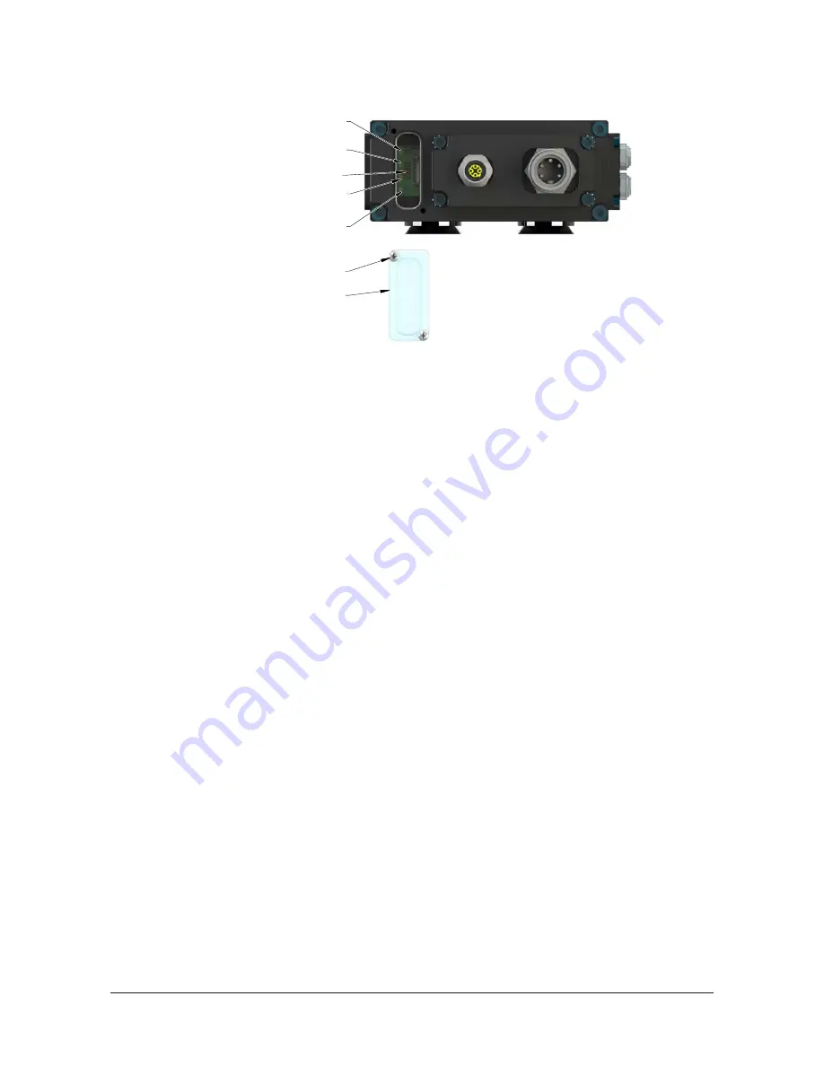
Figure 2.2—Master Module LED and Reset Button
System Failure (SF) LED
Ethernet (E2) LED
Robot-Side Ethernet Port
Ethernet (E1) LED
Tool-Side Ethernet Port
Bus Failure (BF) LED
Reset Button
(Reset to Factory Settings)
(2) M3 Captive Head Screw
Window
2.1.5 Reset-To-Factory Push-Button
A push button, located under the LED window cover between the E2 and BF LED allows the
user to perform a “Reset To Factory” function which clears the PROFINET Name Of Station
and the module’s IP address. This is useful when already configured devices get swapped or a
broken device gets replaced by an already configured device. See
for a detailed device replacement procedure.
After the push button is pressed the SF LED will blink red, indicating that with the next power
cycle the Name of Station and IP address will be cleared.
Make sure to re‑apply the LED window cover after access to the push button is not needed
anymore.
2.2 Arc Prevention Circuit
The DL10 Module incorporates ATI’s exclusive Arc Prevention Circuit. The Arc Prevention Circuit extends
the life of all electrical power contacts by eliminating arcing caused by inductive loads and high inrush
current during coupling/uncoupling. The Arc Prevention Circuit makes it possible to couple/uncouple
without switching power off and prevents damage to the contacts.
In the DL10 Module, the Arc Prevention Circuit controls the ON/OFF status of the following (2) power
signals:
•
Input and Logic power US1+
•
Output power US2+
The behavior of the Arc Prevention circuit is described in the following sections.


