


Manual, FT Sensor, Ethernet Axia
Document #9610-05-Ethernet Axia-05
Pinnacle Park • 1031 Goodworth Drive • Apex, NC 27539 • Tel:+1 919.772.0115 • Fax:+1 919.772.8259 •
• Email:
21
4.2 Connecting Through Ethernet using a Windows Computer
Most of the Ethernet configuration is performed via the Ethernet Axia F/T’s web pages. To initially access
the web pages, configure the sensor to work on the network by assigning an IP address and provide basic
information about the network.
For purposes of this initial connection, the computer should be connected directly to the sensor and
disconnected from the LAN. Temporarily the computer is assigned a fixed IP address of 192.168.1.100. The
Ethernet cable to the sensor is disconnected from the computer during this step.
NOTICE:
If the computer has multiple connections to Ethernet, such as a LAN connection and
a wireless connection, be sure to select the LAN that will be connected to the Ethernet Axia
sensor.
1. Unplug the Ethernet cable from the LAN port on the computer.
2.
Open the computer’s Internet Protocol (TCP IP) Properties window.
•
For a Windows Vista and Windows 7/8/10 operating system, complete the following steps:
a.
From the Start menu, select “Control Panel”.
b.
For Vista, click on “Control Panel Home”.
c.
Click on the “Network and Internet” icon.
d.
Click on the “Network and Sharing Center” icon.
e.
For Vista, click on the “Manage Network Connections” task link. For Windows 7, click on
the “Local Area Connection” link.
f.
For Vista, right-click on “Local Area Connection” and select the “Properties” button. For
Windows 7, click on the “Properties” button.
g.
Select “Internet Protocol Version 4 (TCP/IPv4)” connection item and click on the
“Properties” button.
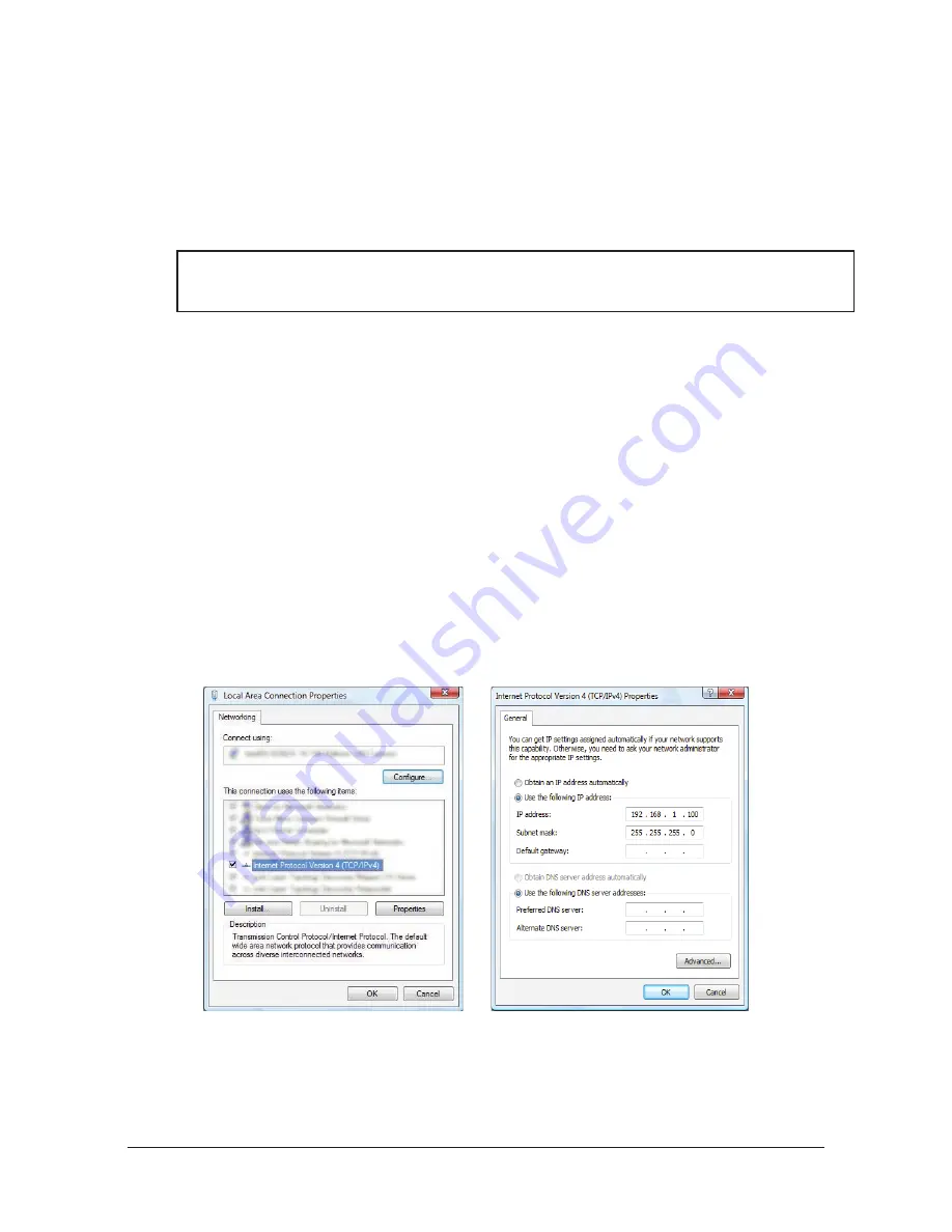
Figure 4.1—Windows Vista and Windows 7/8/10 Networking Information
3.
Record the values and settings shown in the properties window. Save these values so that the computer is
returned to its original configuration.
4. Select the “Use the following IP address” button.
5.
In the IP address: field, enter 192.168.1.100.
6. In the Subnet mask field, enter 255.255.255.0.