background image


® Copyright ATH-Heinl GmbH & Co. KG, 2019, All rights reserved / Misprints and technical changes reserved / As of: 2019-03 

Manufacturer ATH-Heinl GmbH & CO.KG  

- 37 - 

4.0


MAINTENANCE  

 
The user must maintain the machine regularly to ensure safe operation. 

 
Repair work may only be carried out by authorised service partners or after customer consultation with the 
manufacturer. 


Before maintenance and repair work: 

The machine must be disconnected from ALL supply networks 

Pull main switch out of mains plug, if necessary, discharge compressed air from system 

Appropriate measures must be taken against a restart 


Work on electrical elements or on the supply line may only be carried out by experts or 

electricians. 


4.1


Consumables for installation, maintenance and servicing 


Hydraulic Oil 
General 

minimum requirement: 

Eni PRECIS HVLP-D Item No. 00066018 
Summer 

(15° to 45°):   

HVLP-D 46 

(e.g.: Eni PRECIS HVLP-D) 

Winter  

(under 10°):   

HVLP-D 32 

(e.g.: Eni PRECIS HVLP-D) 

 
Minimum requirement

 especially for 2-post lifts:


Eni PRECIS HVLP-D Item No. 00067218 
Summer 

(15° to 45°):   

HVLP-D 32 

(e.g.: Eni PRECIS HVLP-D) 

Winter  

(under 10°):   

HVLP-D 22 

(e.g.: Eni PRECIS HVLP-D)


Preservative for ropes, welds, screws, corners, edges and cavities. 

Minimum requirement: 

Petec spray translucent - 500 ml Item No. 73550 / Petec wall inlet translucent - 1000 ml 

Item No. 

73510 
Petec UBS pistol 


Item No. 98507 


Slideway lubricant  

Minimum requirement: 

STORER WHS 2002 White EP high performance grease. Item No. KPF1-2K-20


Lubricant for bushes, chains, rollers & moving parts 

Minimum requirement: 
White ultra lube, 500 ml aerosol. Item No. 34403 – WUL – White Ultra Lube   


Floor anchor  

Minimum requirement

 for lifting platforms:


Fischer FIS A M 16 x 200 galvanised in combination with Fischer Superbond reaction cartridge 
 
Minimum requirement for

 passenger car and passenger car/truck balancing machine:


Impact anchor M8 x 100 
 
Minimum requirement 

for truck mounting machine:


Impact anchor M12 x 100 

Compressed air system


Summary of Contents for W42

Page 1: ...OPERATING INSTRUCTIONS ATH W42 ...

Page 2: ... 3 0 OPERATION 35 3 1 Operating Instructions 35 3 2 Basic Information 36 4 0 MAINTENANCE 37 4 1 Consumables for installation maintenance and servicing 37 4 2 Safety Regulations for Oil 38 4 3 Notes 39 4 4 Maintenance or Service Plan 39 4 5 Troubleshooting Error Display and Solutions 40 4 6 Maintenance and Service Instructions 42 4 7 Disposal 43 5 0 EG EU KONFORMITÄTSERKLÄRUNG EC EU DECLARATION OF ...

Page 3: ...GRAL PART OF THE MACHINE THEY MUST BE READ AND UNDERSTOOD BY THE USER NO LIABILITY IS ASSUMED FOR ANY DAMAGES CAUSED BY FAILURE TO FOLLOW THESE INSTRUCTIONS OR THE VALID SECURITY PROVISIONS WARNING Follow the instructions to prevent injury or damage TIP Provides more information on functionality and tips for using the device efficiently Appropriate protective clothing must be worn for all work on ...

Page 4: ...9 03 Manufacturer ATH Heinl GmbH CO KG 4 1 2 Description 1 Main switch with emergency stop function used to switch the balancing machine on and off 2 Cone intake 3 Weight storage 4 Wheel protector 5 Plunge 6 Balancing shaft 7 Display 8 Control 9 Brake pedal 10 Broad measurement optional 7 2 1 8 3 5 9 6 4 10 ...

Page 5: ...O KG 5 1 Display INTERNAL imbalance 2 Display EXTERNAL imbalance 3 Display position of the INTERNAL imbalance 4 Display position of the EXTERNAL imbalance 5 Display mode 6 Indicator light for measurement unit mm or inches 7 Display STATIC imbalance 8 Indicator light for measurement unit g or ounces 9 Display weight position 1 3 4 2 5 6 7 8 9 ...

Page 6: ...l GmbH CO KG 6 Distance between rim and machine Rim width Rim diameter Calibration button Self test Change between DYNAMIC STATIC ALU programme selection Optimisation programme Display precise imbalance 5 g Change size entries Button Button Only operate the buttons with your fingers Under no circumstances should sharp objects be used ...

Page 7: ... below there are 2 easy ways to mount the wheel a The first way of mounting a wheel is shown opposite Using this method the wheel rim is stretched onto the balancing shaft from the exterior If you are using the largest cone the extension piece for the clamping cone must also be used This method increases the risk of clamping errors and is therefore only recommended for use with steel rims b When u...

Page 8: ...culate the radial and lateral run out of an aluminium wheel rim The balancing weights are positioned at a pre defined point ALU 2 These functions calculate the radial and lateral run out of an aluminium wheel rim The balancing weights are positioned at a pre defined point ALUS These functions calculate the radial and lateral run out of an aluminium wheel rim The balancing weights are positioned at...

Page 9: ... Co KG 2019 All rights reserved Misprints and technical changes reserved As of 2019 03 Manufacturer ATH Heinl GmbH CO KG 9 1 3 4 Entry of the tyre sizes a Basics In motorcycle mode an optional measuring tip 100 mm must be used ...

Page 10: ...y the machine The rim width must then be entered using the B B buttons The following data must be recorded in ALU2 and ALUS mode A Distance between the machine and the first adhesive point B Distance between the machine and the second adhesive point D Rim diameter dE Rim diameter at the second adhesive point All wheel values are recorded by the automatic plunge During the measurement process first...

Page 11: ...al weight DYN 12 o clock position laser 12 o clock position STA 12 o clock position laser ALU1 12 o clock position laser 12 o clock position ALU2 12 o clock position laser Weight recording on the gauge arm ALUS Weight recording on the gauge arm Weight recording on the gauge arm a HID function The HID function allows you to position the external balancing weight in a hidden spot behind the spokes T...

Page 12: ...irm this position using ALU The display will then show SPO 2 Now turn the wheel until the right spoke is at the 12 o clock position Confirm this position using ALU The display will then show the INTERNAL IMBALANCE and SPL in the third field By turning the wheel until all the diodes for the external position light up the respective value will also be displayed Next position the weight against the g...

Page 13: ...ance of the wheel using the OPT function The unbalance of the wheel rim is evened out with the unbalance of the tyre After a balancing run you can test the static imbalance by pressing the F button If the imbalance is over 30 g an optimisation process is recommended Make a mark at the position of the valve on the tyre the entry cover of the balancing machine and the wheel rim so that the mark line...

Page 14: ...sation that has been calculated will then appear on the display Turn the wheel when stretched until the display opposite appears Mark the TYRE at the 12 o clock position Turn the wheel when stretched until the display opposite appears Mark the WHEEL RIM at the 12 o clock position Remove the wheel from the balancing machine Measure the air pressure and remove the tyre using a suitable tyre changing...

Page 15: ...tor 0 25 kW Electric system 1 220 V 50 Hz Power consumption 15 W in standby mode Balancing speed 180 rpm Protection type IP 54 Sound pressure level during operation 70 dB A Shaft diameter 40 mm Balancing programmes Dynamic mode standard Static mode Standard ALU 1 ALU 2 mode ALU S mode Additional functions OPT optimisation mode HID mode positioning behind spokes Setting the measurement units to g o...

Page 16: ... Copyright ATH Heinl GmbH Co KG 2019 All rights reserved Misprints and technical changes reserved As of 2019 03 Manufacturer ATH Heinl GmbH CO KG 16 1 5 Scale Drawing 800 mm 1330 mm 1700 mm ...

Page 17: ... must be checked after completion of the installation handover if necessary briefing and then regularly in accordance with the applicable regulations and legal provisions in the country of operation by a suitable and approved company or facility 2 1 Transport Storage Conditions When transporting and positioning the machine always use suitable lifting and material handling equipment and consider th...

Page 18: ...uitable lifting device possibly with a stopping rope to lower the machine from the pallet frame The packaging material used for the machine should be stored carefully Keep the packaging material out of the reach of children as it may be hazardous You can view the current contents of the packaging in the image opposite There is also an accessory pack INSIDE the balancing machine In order to retriev...

Page 19: ... 2019 All rights reserved Misprints and technical changes reserved As of 2019 03 Manufacturer ATH Heinl GmbH CO KG 19 2 3 Delivery Contents Wheel protector Consists of two plastic arcs and a frame with handle LED monitor with holder ...

Page 20: ...idth 3 14 inches Packaging dimensions 455 x 430 x 50 mm Protector mechanism Fixing screw for protector Fixing Packaging dimensions 350 x 230 x 160 mm Accessories box Packaging dimensions 385 x 240 x 280 mm Adhesive weight remover 5 g impact weight 10 g impact weight 35 g impact weight 50 g impact weight 100 g impact weight Weight pliers Hexagon key Tensioned cover Rubber lip for tensioned cover Te...

Page 21: ...must be set up on sufficiently firm ground if necessary according to the minimum requirements of the information given in the foundation plan In addition to the ground conditions the guidelines and instructions of the accident prevention regulations as well as the workplace regulations must be observed when selecting an installation site When assembling on floor coverings check their load bearing ...

Page 22: ...d if necessary according to the minimum requirements of the information given in the foundation plan The machine must be fastened at the points provided with suitable or specified fastening material In addition to the ground conditions the guidelines and instructions of the accident prevention regulations as well as the workplace regulations must be observed when selecting an installation site Whe...

Page 23: ...ce unit must be set correctly and checked The compressed air maintenance unit must be serviced at regular intervals The maximum or minimum pressure ensures perfect functioning without any damage 2 8 Hydraulic Connection Before the system is put into operation or operated for the first time with oil the following must be observed with regard to the optimal trouble free and almost air free functioni...

Page 24: ...up the balancing machine a Remove the balancing machine from the shipping pallet Use the support points that are specially designed for this purpose to do this Under no circumstances should the machine be lifted on other points e g the shaft the display or the accessory panel b The machine must be firmly positioned on the ground using the special support points and if necessary washers must be use...

Page 25: ...anges reserved As of 2019 03 Manufacturer ATH Heinl GmbH CO KG 25 2 9 3 Assembling the balancing shaft Clean the entry point before assembling the balancing shaft Before fixing ensure that both marks match up Now fix the balancing shaft with the clamping cone using the screw provided ...

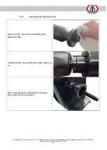
Page 26: ... 2 9 4 Assembling the wheel protector Remove the upper cover from the protector mechanism Secure the cover using the four screws washers and spring washers provided Connect these to the corresponding connection port and affix the cover again Remove the handle from the frame of the wheel protector Remove the fixing screw from the protector mechanism ...

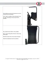
Page 27: ...he rear part of the protector over the entry point for the protector Then take the protector frame and guide it into the entry point through the rear part of the protector Now slide the front half over the protector Next connect both parts and secure these using both screws Attach the fixing screw to the entry point again Mount the handle back onto the protector ...

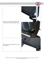
Page 28: ...r screws provided Remove the two upper screws on the cover of the holder in order to guide the connecting cables through the inside cable channel Connect the cables to the machine Next fix the monitor to the holder using the screws provided Then connect the monitor Finally both upper screws on the holder can be reattached 2 9 6 Assembling the tyre width gauge optional First mount the arm holder on...

Page 29: ... reserved Misprints and technical changes reserved As of 2019 03 Manufacturer ATH Heinl GmbH CO KG 29 Next secure the measurement gauge to the wheel protector frame using two Allen screws Now secure the connecting cable to the frame using cable ties ...

Page 30: ... gauge In order to access the system you must press the key combination shown opposite 1 First the C button and then the T button 2 The CAL CAL displays will appear and the indicator lights flash 3 Release the buttons only when the indicator light is steady 4 Press the A button 5 Press the A button 6 Press the ALU button 7 Press the A button once 1x Turn the wheel rim width gauge on off using B B ...

Page 31: ... The machine MUST be calibrated after securing and at a minimum before the season or after a longer period of use Clamp a wheel that has already been balanced 14 or 15 and enter the wheel values see Usage Point 4 In order to access the calibration system you must press the key combination shown opposite 1 First the C button and then the T button 2 The CAL CAL displays will appear and the indicator...

Page 32: ... Attach the calibration weight 100 g to the outside of the wheel rim Press the START button again or close the wheel protector in order to terminate the calibration process 2 9 10 Service calibration of the gauge 1 Position the gauge to 0 2 Press the key combination STOP 5 g 3 The display shown opposite will appear 4 Position the gauge to 100 mm 5 Press the ALU button 6 The display shows CAL 215 7...

Page 33: ...onfirm with ALU 12 Then secure an appropriate wheel e g 16 on the machine 13 Next position the plunge on the edge of the wheel rim 14 Press the ALU button 15 The display shows CAL End 16 If the display shows CAL 10 this means that the calibration has been unsuccessful and must be repeated 2 9 11 Service calibration of the width gauge optional 1 Press the key combination STOP OPT 2 The display show...

Page 34: ...reshold be set to 10 g Why Because the machine records the dynamic and static imbalance the operating characteristics of the wheel change when the weights are affixed Because the weights are positioned further towards the middle of the wheel rim the weights automatically achieve greater and more precise balancing results Because the machine requires the balancing weights at one point and there are...

Page 35: ...ng the tyre set up a guard to catch any flying parts Keep people out of the danger area Tyre filling must be monitored and the maximum permissible assembly air pressures must not be exceeded Only operate motor driven wheel balancers with a protective hood For large wheels of trucks and self driving machines On machines with vertical wheels work with heavy tyres for example EM tyres must be carried...

Page 36: ...l components for damage If necessary observe special manufacturer instructions for mounting or dismounting of vehicle specific work An important part of the guarantee warranty is fulfilment of the maintenance plan This includes in particular ensuring cleanliness corrosion protection checks and repairing damages immediately if required During operation attention should always be paid to hazards As ...

Page 37: ...46 e g Eni PRECIS HVLP D Winter under 10 HVLP D 32 e g Eni PRECIS HVLP D Minimum requirement especially for 2 post lifts Eni PRECIS HVLP D Item No 00067218 Summer 15 to 45 HVLP D 32 e g Eni PRECIS HVLP D Winter under 10 HVLP D 22 e g Eni PRECIS HVLP D Preservative for ropes welds screws corners edges and cavities Minimum requirement Petec spray translucent 500 ml Item No 73550 Petec wall inlet tra...

Page 38: ...em No 98507 Care and protection of metals painted or powder coated surfaces in the tread area and plastic parts Minimum requirement Valet Pro Classic Protectant Plastic Sealant 500 ml 4 2 Safety Regulations for Oil Always observe the legal requirements or regulations for handling used oil Always dispose of used oil through a certified organisation In the case of leaks oil must be collected immedia...

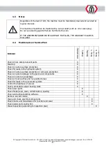
Page 39: ...hs Every 6 months Check of ALL safety relevant parts X Cleaning X Check or restore surface protection X Check for leaks in the hydraulic system X Check or restore surface protection or corrosion protection X Check or restore damage to the paint and components X Check or restore rust damage X Check or treat cavities and non painted areas X Check for leaks in the pneumatic system X Control the tight...

Page 40: ...ror Code Reason Err 1 See troubleshooting Err 2 1 There is no wheel on the shaft or wheel is too light 2 Balancing shaft is not tightened 3 Wheel was not sufficiently secured 4 Ribbed belt not or too weakly tensioned Err 3 Wheel imbalance is too great Err 4 Defective pressure sensor Rotates in wrong direction Err 5 Wheel cover is not closed Err 7 Saved data has been deleted Err 8 100g weight missi...

Page 41: ...Engine does not or only sporadically brakes Brake resistor defective or not connected Check brake resistor or connection Motor makes noises Brake resistor defective or not connected Check brake resistor or connection Damaged motherboard Contact ATH service The condenser is defective or not connected Check condenser or connection Building circuit breaker blows Main machine switch is not connected c...

Page 42: ... data The working pressure can be adjusted with a pressure regulator A Pull the pressure regulator upwards to make adjustments Turn the knob clockwise to increase the pressure in the machine turn it counter clockwise to decrease OILER Check the oil level in the oil reservoir 3 Remove the oil reservoir Now refill the tank with a pneumatic oil with a viscosity of SAE20 Check the injection quantity o...

Page 43: ...not move to the side 6 Remount the cover Changing the fuses 1 Carefully remove the cover weight storage 2 Remove the fuse from the electricity supply board 3 Swap the old fuse for a new fuse ensuring that the ratings of the fuses are the same If the problem persists please contact the service team 4 7 Disposal Remove the air and power supply Remove all non metallic substances and store them in acc...

Page 44: ...al Safety and Health regulations of the of Directive 2000 60 EC and the harmonized standards listed below Beschreibung der Maschine Descriptions of the machine Rad Wuchtmaschine Wheel balancer Typbezeichnung Model name ATH W42 Der oben beschriebene Gegenstand der Erklärung erfüllt die folgenden einschlägigen Harmonisierungs rechtsvorschriften der Union The object of the declaration described above...

Page 45: ...hts reserved Misprints and technical changes reserved As of 2019 03 Manufacturer ATH Heinl GmbH CO KG 45 6 0 APPENDIX 6 1 Pneumatic circuit diagram Not relevant 6 2 Electric circuit diagram Not relevant 6 3 Hydraulic circuit diagram Not relevant ...

Page 46: ...cription of required spare parts Spare part Item number Amount IMPORTANT Damage resulting from improper handling lack of maintenance or mechanical damage is not covered by the warranty For systems that have not been installed by an ATH approved installer the warranty is limited to the provision of the necessary spare parts Transport damages Visible defect visible transport damage note on freight f...

Page 47: ...follow the instructions in this manual and or other accompanying instructions Normal wear and tear on parts requiring service to keep the product in safe working condition Any component that has been damaged during transport Other components that have not been explicitly listed but are considered to be general consumables Water damage caused by e g rain excessive humidity corrosive environments or...

Page 48: ...n regularly in accordance with the applicable regulations and legal provisions in the country of operation by a suitable and approved company or facility In the case of changes or extensions to the product type an additional inspection book must be maintained and accepted Scope of Inspection In addition to perfect function cleanliness and maintenance requirements it is vital that the safety releva...

Page 49: ... The warranty is only valid in conjunction with compliance and evidence of proper assembly handover and if necessary training as well as yearly maintenance carried out by an expert authorised by the manufacturer The interval between services must not exceed 12 months In case of non standard use or multi shift or seasonal use a bi annual inspection and maintenance must be arranged Warranty claims a...

Page 50: ...n Condition aggregate Condition drive Condition motor Condition transmission Condition cylinder Condition valve Condition electrical control Condition electric buttons Condition electric switches Condition electric lines Condition hydraulic lines Condition hydraulic screws Condition pneumatic lines Condition pneumatic screws Condition tightness Condition bolts and bearings Condition consumables Co...

Page 51: ...____________________ _________________________________________________________________________________ Inspection contents functional and visual inspection according to specifications Pending partial inspection _________________________________________________________________________________ _________________________________________________________________________________ There were no concerns ar...

Page 52: ...__________________ _________________________________________________________________________________ Inspection contents functional and visual inspection according to specifications Pending partial inspection _________________________________________________________________________________ _________________________________________________________________________________ There were no concerns aris...

Page 53: ...__________________ _________________________________________________________________________________ Inspection contents functional and visual inspection according to specifications Pending partial inspection _________________________________________________________________________________ _________________________________________________________________________________ There were no concerns aris...

Page 54: ...__________________ _________________________________________________________________________________ Inspection contents functional and visual inspection according to specifications Pending partial inspection _________________________________________________________________________________ _________________________________________________________________________________ There were no concerns aris...

Page 55: ... Copyright ATH Heinl GmbH Co KG 2019 All rights reserved Misprints and technical changes reserved As of 2019 03 Manufacturer ATH Heinl GmbH CO KG 55 9 0 SPARE PART BOOK ...

Page 56: ... Copyright ATH Heinl GmbH Co KG 2019 All rights reserved Misprints and technical changes reserved As of 2019 03 Manufacturer ATH Heinl GmbH CO KG 56 Maschine Machine ...

Page 57: ...20 Messarm komplett Distance Arm Assembly 1 01 09 RSM0007 520202020 Schutzbogen Mechanismus komplett Hood Mounting Assembly 1 01 10 RGW0062 520201060 Gewindewelle mit Spannglocke Main Shaft Spindle 1 01 11 RMO0755 520212010 Motor 220V Motor 1 01 12 RBM0001 520206010 Bremsmechanismus komplett Braking System 1 01 13 RRP0138 520215020 Rotationsplatine Encoder 1 01 14 RHS0001 520216030 Hauptschalter O...

Page 58: ... Copyright ATH Heinl GmbH Co KG 2019 All rights reserved Misprints and technical changes reserved As of 2019 03 Manufacturer ATH Heinl GmbH CO KG 58 Anzeige Display ...

Page 59: ...7 Kreuzschlitz Schraube M4x16 Cross recessed pan head screw M4x16 1 02 12 30201082 Innensechskant Schraube M10X20 SHCS M10X20 2 02 13 30301055 Selbstsichernde Mutter M10 Secure nut M10 2 02 14 RHM1095 530211200 Display Halterung Display Support 1 02 15 30201004 Innensechskant Schraube M4X12 SHCS M4X12 6 02 16 RHM1096 530211209 Abdeckung Kabelkanal Display Support Cover 1 02 17 30201338 Kreuzschlit...

Page 60: ... Copyright ATH Heinl GmbH Co KG 2019 All rights reserved Misprints and technical changes reserved As of 2019 03 Manufacturer ATH Heinl GmbH CO KG 60 Zubehör Accessories ...

Page 61: ...0060 22102001 Inbusschlüssel 12mm Allen Wrench 12mm 1 03 11 RIS0063 22102002 Inbusschlüssel 6mm Allen Wrench 6mm 1 03 12 RIS0065 22102003 Inbusschlüssel 4mm Allen Wrench 4mm 1 03 13 RIS0066 22102004 Inbusschlüssel 3mm Allen Wrench 3mm 1 03 14 RGZ0057 22102005 Gewichtszange Weight Hammer 1 03 15 RSF0208 20701019 Spannfeder Ø 40mm Mounting Spring Ø40mm 1 03 16 RPG0195 22102006 Schlaggewicht PKW 100g...

Page 62: ... Copyright ATH Heinl GmbH Co KG 2019 All rights reserved Misprints and technical changes reserved As of 2019 03 Manufacturer ATH Heinl GmbH CO KG 62 Schutzbogen Mechanismus Hood mounting ...

Page 63: ...04 07 RMS6000 21006031 Mikroschalter V 156 1C25 Hood Switch V 156 1C25 1 04 08 RSM0006 530208002 Schutzbogen Anschlag Hood Cam Stop 1 04 09 RSM0007 20601034 Schutzbogen Mechanismus komplett Hood Cam 1 04 10 RSM2001 21301004 Einschrauböse Adjustable Eye Bolt 1 04 11 30201063 Selbstschneidende Schraube M8x20 HHB M8x20 4 04 12 30202025 Innensechskant Schraube M8x12 Hexagon socket set screw M8x12 2 04...

Page 64: ... Copyright ATH Heinl GmbH Co KG 2019 All rights reserved Misprints and technical changes reserved As of 2019 03 Manufacturer ATH Heinl GmbH CO KG 64 Schutzbogen Hood ...

Page 65: ...tzbogen Wheel Hood Support 1 05 04 30201084 Innensechskant Schraube M10x30 SHCS M10x30 1 05 05 30501006 Beilagscheibe 10mm Washer Flat 10mm 3 05 06 30201337 Kreuzschlitz Schraube M4x16 Cross recessed pan head screw M4x16 1 05 07 RSB0008 20601049 Halter für Messarm OPTIONAL External Gauge Clip OPTIONAL 1 05 08 30201092 Innensechskant Schraube M10x70 SHCS M10x70 2 05 09 30502006 Federscheibe 10mm Wa...

Page 66: ... Motor JY7116 220V Motor JY7116 220V 1 06 02 RMH0123 530206002 Motorhalterung Motor Basement 1 06 03 RRR0134 530206003 Rippenriemenrad Motor Belt Pulley 1 06 04 30701010 Passfeder 5x5x30 Key 5x5x30 1 06 05 30201043 Innensechskant Schraube M6x16 SHCS M6x16 4 06 06 30502004 Federscheibe 6mm Washer Spring 6mm 4 06 07 30501004 Beilagscheibe 6mm Washer Flat 6mm 4 06 08 RRR0133 20403001 Rippenriemen 4PJ...

Page 67: ...atine 64T Tooth 64T 1 07 04 RWA0002 530207005 Abdeckung für Wuchtwelle Bear Cover 1 07 05 30201044 Innensechskant Schraube M6x20 SHCS M6x20 3 07 06 30303101 Mutter M30x1 5 Nut Round M30x1 5 1 07 07 30604023 Sprengring 30mm Snap Ring 30mm 1 07 08 RWL0845 30802002 Kugellager 6006 Bearing 6006 1 07 09 RWL0184 30802001 Kugellager 6005 Bearing 6005 1 07 10 30604105 Sprengring 25mm Snap Ring 25mm 1 07 1...

Page 68: ...M10 5 08 02 530207043 Beilagscheibe Sensor flat washer 2 08 03 RPA0128 21006032 Piezo sensoren Piezo Sensors 1 08 04 21301007 horizontal vertikal Horizontal Vertical 1 08 05 21301008 Ø10 Ø 10 3x0 75mm x1 5m Ø10 Ø 10 3x0 75mm x1 5m 1 08 06 RPA0129 21006033 Piezo Sensor Aufnahmewelle horizontal Vertical shaft 1 08 07 RPA0130 20402015 Piezo Sensor Aufnahmewelle vertikal Horizontal shaft 1 08 08 30502...

Page 69: ...HCS M4x8 2 09 02 30502002 Federscheibe 4mm Washer Spring 4mm 2 09 03 30501002 Beilagscheibe 4mm Washer Flat 4mm 2 09 04 RRP0138 21003004 Rotationsplatine 64T Encoder Board 64T 1 09 05 30301101 Mutter M3 Nut M3 2 09 06 30502001 Federscheibe 3mm Washer Spring 3mm 2 09 07 30501001 Beilagscheibe 3mm Washer Flat 3mm 2 09 08 RRP0139 530207003 Aufnahme für Rotationsplatine Encoder Board Support 1 09 09 3...

Page 70: ... Copyright ATH Heinl GmbH Co KG 2019 All rights reserved Misprints and technical changes reserved As of 2019 03 Manufacturer ATH Heinl GmbH CO KG 70 Bremse Brake ...

Page 71: ...21006031 Mikroschalter Brake Switch 1 10 13 RBZ0001 530202005 Zugstange für Bremse Braking Rod 1 10 14 30301138 Mutter M12 Nut M12 1 10 15 30101024 Selbstschneidende Schraube M6x25 HHB M6x25 1 10 16 RBA0007 530202012 Achse für Bremspedal Brake Fix Axle 1 10 17 30301101 Mutter M3 Nut M3 2 10 18 30301105 Mutter M6 Nut M6 2 10 19 30201043 Innensechskant Schraube M6x16 SHCS M6x16 2 10 20 RBA0008 53020...

Page 72: ... Copyright ATH Heinl GmbH Co KG 2019 All rights reserved Misprints and technical changes reserved As of 2019 03 Manufacturer ATH Heinl GmbH CO KG 72 Stromversorgungsplatine Power board ...

Page 73: ... 05 30101022 Selbstschneidende Schraube M6x16 HHB M6x16 4 11 06 30301106 Mutter M8 Nut M8 4 11 07 RWI0183 21002001 Widerstand 100W 15Ω RXG 100 15RJ Resistance 100W 15Ω RXG 100 15RJ 1 11 08 RSP0170 530206001 Aufnahmeplatte für Stromversorgungsplatine Power Board Liner 1 11 09 30201614 Kreuzschlitz Schraube M3x25 Cross recessed socket screw M3x25 5 11 10 RSP0171 530206056 Kühler für Stromversorgungs...

Page 74: ... Copyright ATH Heinl GmbH Co KG 2019 All rights reserved Misprints and technical changes reserved As of 2019 03 Manufacturer ATH Heinl GmbH CO KG 74 Abstandslehre Measuring arm ...

Page 75: ...tance Arm End Metal Plate 1 12 17 30201043 Innensechskant Schraube M6x16 SHCS M6x16 2 12 18 RGA0002 530204009 Zahnstange für Abstandslehre Distance Arm Gear Rail 1 12 19 RAA0001 530204004 Aufnahme für Abstandslehre Distance Arm Basement 1 12 20 30204001 Kreuzschlitz Schraube ST2 9x6 5 Cross recessed tapping screw ST2 9x6 5 5 12 21 RPH0003 530204018 Beilagscheibe für Abstandslehre Distance Arm Pad ...

Page 76: ...0206034 Kunststoffabdeckung Laser LED Threaded Shaft Plastic Cover 1 13 03 RLG0001 530206033 Grundplatte für Laser Laser Basement Plate 1 13 04 RLA0001 2106035 Laser Ø12x35 5V Laser Line Optical Transmitter Ø12x35 5V 1 13 05 RLA0002 530206032 Aufnahme für Laser Laser Basement 1 13 06 30201335 Kreuzschlitz Schraube M4x12 Cross recessed pan head screw M4x12 2 13 07 30202301 Madenschraube M5x5 Hexago...

Page 77: ...As of 2019 03 Manufacturer ATH Heinl GmbH CO KG 77 Steuerplatine Computer board ATH Referenz Bezeichnung Description x 14 01 30201614 Schraube M3x25 Screw M3x25 4 14 02 30502001 Federscheibe 3 Spring washer 3 8 14 03 30301101 Mutter M3 Nut M3 12 14 04 RSP0168 21003016 Steuerplatine Computer board 1 ...

Page 78: ... Copyright ATH Heinl GmbH Co KG 2019 All rights reserved Misprints and technical changes reserved As of 2019 03 Manufacturer ATH Heinl GmbH CO KG 78 10 0 NOTES ...

Page 79: ... Copyright ATH Heinl GmbH Co KG 2019 All rights reserved Misprints and technical changes reserved As of 2019 03 Manufacturer ATH Heinl GmbH CO KG 79 ...

Page 80: ... Copyright ATH Heinl GmbH Co KG 2019 All rights reserved Misprints and technical changes reserved As of 2019 03 Manufacturer ATH Heinl GmbH CO KG 80 ...

Reviews: