background image

VM0808 User Manual

6

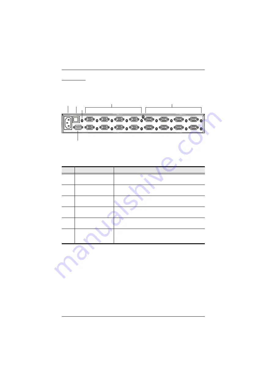
Rear View

No.

Component

Description

1

Power Socket

This is a standard 3-pin AC power socket. The power 
cord from an AC source plugs in here.

2

Power Switch

This is a standard rocker switch that powers the unit 
on and off.

3

External IR Receiver 
Port

3.5 mm Mini Stereo Jack which connects the IR 
Receiver unit included with your product. 

4

RS-232 Serial Port

This serial remote port is for input source selection and 
high-end system control.

5

Audio/Video Input 
Ports

The VGA ports are for connecting your input source. 
The Mini Stereo Jack ports are for the audio source.

6

Audio/Video Output 
Ports

The VGA ports are for connecting your output 
displays. The Mini Stereo Jack ports are for the audio 
speakers.

1

2

3

4

5

6

Summary of Contents for VM0808

Page 1: ...8x8 Video Matrix Switch Audio VM0808 User Manual www aten com ...

Page 2: ...nce when the equipment is operated in a commercial environment This equipment generates uses and can radiate radio frequency energy and if not installed and used in accordance with the instruction manual may cause harmful interference to radio communications Operation of this equipment in a residential area is likely to cause harmful interference in which case the user will be required to correct ...

Page 3: ...e the buyer and not the manufacturer its distributor or its dealer assumes the entire cost of all necessary servicing repair and any incidental or consequential damages resulting from any defect in the software The manufacturer of this system is not responsible for any radio and or TV interference caused by unauthorized modifications to this device It is the responsibility of the user to correct s...

Page 4: ...l thoroughly and follow the installation and operation procedures carefully to prevent any damage to the unit and or any of the devices connected to it Features may have been added to the VM0808 since this manual was published Please visit our website to download the most up to date version Copyright 2012 ATEN International Co Ltd Manual Date 2012 11 14 ATEN and the ATEN logo are registered tradem...

Page 5: ...duction Overview 1 Features 2 Requirements 3 Source Devices 3 Display Devices 3 Cables 3 Source Device Operating Systems 4 Components 5 Front View 5 Rear View 6 IR Remote Control 7 2 Hardware Setup Rack Mounting 8 Cable Connections 10 3 Operation Overview 11 Front Panel Operation 11 Basic Navigation 11 Menu Organization 12 Enter Password 13 Main Screen 14 Video In Selection 14 Independent Audio In...

Page 6: ...utput port 26 Power on off individual Output displays 26 Power on off all Output displays 27 4 RS 232 Commands Serial Control Protocol Commands 28 Configuring the Serial Port 28 Switch Port Commands 28 EDID Commands 30 Mute Commands 31 Save Load Profile Commands 32 Appendix Safety Instructions 34 General 34 Rack Mounting 36 Technical Support 37 International 37 North America 37 Specifications 38 L...

Page 7: ... control components are described Chapter 2 Hardware Setup describes how to set up your VM0808 installation and all the necessary steps Chapter 3 Operation explains the fundamental concepts involved in operating the VM0808 via the front panel LCD display and with the IR remote control Chapter 4 RS 232 Protocol Commands provides a complete list of the serial control protocol commands used when util...

Page 8: ...Indicates keys you should press For example Enter means to press the Enter key If keys need to be chorded they appear together in the same bracket with a plus sign between them Ctrl Alt 1 Numbered lists represent procedures with sequential steps Bullet lists provide information but do not involve sequential steps Indicates selecting the option on a menu or dialog box for example that comes next Fo...

Page 9: ...udio matrix capabilities The VM0808 is a smart audio video solution that offers an easy and affordable way to route any of 8 audio video sources to any of 8 audio displays in any matrix combination As a Matrix Switch each input can be independently connected to any or all outputs and the audio inputs from each source device can also be switched independently giving you the ultimate in flexibility ...

Page 10: ... 1920 x 1200 Features EDID expert technology to set up different video configurations via different EDID modes Supports up to 500 MHz bandwidth Supports stereo audio Independent switching of audio and video sources each input can be independently connected to any or all outputs for flexibility Power On Detection If one of the video sources is powered off the VM0808 automatically switches to the ne...

Page 11: ...puter or A V source device with VGA and stereo output Display Devices A VGA SVGA XGA SXGA UXGA WUXGA or multisync display device with an HDB 15 connector Stereo speakers Cables Use VGA Audio RS 232 cables to connect the computer or other audio video source device to the VM0808 Note Cables are not provided in the VM0808 package ...

Page 12: ...e shown in the table below OS Version Windows 2000 and higher Linux RedHat 6 0 and higher SuSE 8 2 and higher Mandriva Mandrake 9 0 and higher UNIX AIX 4 3 and higher FreeBSD 3 51 and higher Sun Solaris 8 and higher Novell Netware 5 0 and higher Mac OS 9 and higher DOS 6 2 and higher ...

Page 13: ...08 MENU Press to invoke the Menu page Main Screen PROFILE Press to switch between the video source Profile Selection list ESC Press to cancel the current selection or exit without saving changes ENTER Press to confirm the current selection Tuner Dials IN OUT to navigate up down left and right or scroll selected options within the LCD display For full details see Front Panel Operation page 11 Note ...

Page 14: ...t 3 5 mm Mini Stereo Jack which connects the IR Receiver unit included with your product 4 RS 232 Serial Port This serial remote port is for input source selection and high end system control 5 Audio Video Input Ports The VGA ports are for connecting your input source The Mini Stereo Jack ports are for the audio source 6 Audio Video Output Ports The VGA ports are for connecting your output display...

Page 15: ...r off by individual port or all ports see Remote Control Operation page 26 2 Output Pushbuttons 1 8 Output display Pushbutton 1 8 to change Input source for Output displays see Remote Control Operation page 26 3 Input Pushbuttons 1 8 Input source Pushbutton 1 8 to change Input source of an Output display see Remote Control Operation page 26 1 2 3 ...

Page 16: ...supplied with the Rack Mount Kit to screw the rack mounting brackets onto the front of the unit Continues on next page 1 Important safety information regarding the placement of this device is provided on page 34 Please review it before proceeding 2 Make sure that the power to all devices connected to the installation are turned off You must unplug the power cords of any computers that have the Key...

Page 17: ...Chapter 2 Hardware Setup 9 2 Position the unit in the front of the rack and align the holes in the mounting brackets with the holes in the rack 3 Screw the mounting brackets to the rack ...

Page 18: ...RS 232 serial cable to connect the computer or serial controller to the VM0808 s female RS 232 port 2 Connect up to 8 video audio sources to the VGA Audio Input ports 3 Connect up to 8 display audio devices to the VGA Audio Output ports 4 Connect the IR Receiver into the External IR Receiver Input Port 5 Plug the power cord supplied with the package into the VM0808 s 3 prong AC socket and then int...

Page 19: ...curity information loading saving profiles and setting up the Profile Selection list Basic Navigation The VM0808 s front panel display operation is easy and convenient Please note the following front panel button and dial operations Use the MENU pushbutton to access the Menu page options Switch Audio only Set Serial Port Operation Mode Security Mode Save Load Profile and Profile Selection Use the ...

Page 20: ...g PROFILE cycles through the Profiles added to the Profile Selection list Switch Audio Only Select Audio IN 1 8 or N A Set Serial Port Default Serial Setting Yes No Baud Rate 9600 19200 38400 115200 Operation Mode Power On Detection Off On EDID Auto Default Port1 Remix Security Mode Password Required Yes No Change Password Old Password New Password Save Load Profile Save to a Profile No 0 31 Call ...

Page 21: ...ault password is 1234 To enter a password do the following 1 Turn the front panel OUT dial left or right to move the cursor position 2 Turn the front panel IN dial left or right to cycle through the numbers 3 Press and Release the OUT IN or ENTER pushbutton to confirm the password and continue to the Main Screen Note 1 If you enter an incorrect password re enter the correct password over the incor...

Page 22: ... you to the Main screen Video In Selection To select which input source displays on each output port from the main screen do the following 1 Turn the OUT dial to select an output port s corresponding input port 2 When the cursor highlights your selected input port use the IN dial to cycle through the available input sources Options are Ports 1 8 NA none 3 Press the OUT IN or ENTER pushbutton to co...

Page 23: ... to the Output port s audio you would like to change 3 When the cursor highlights your selected input port use the IN dial to cycle through the available audio Input sources to associated it to the Output port above it Options are Ports 1 8 NA none 4 Press OUT IN or ENTER pushbuttons to confirm your selection to switch audio to the selected port 5 Press ESC to return to the Menu page ESC ENTER PRO...

Page 24: ...Setting press and release the OUT IN or ENTER pushbutton to access the options The Default Serial Setting option flashes 2 Turn the front panel IN OUT dial left or right to select Yes or No 3 Press and Release the OUT IN or ENTER pushbutton to confirm the change Note The default serial setting is No Baud Rate To set the VM0808 s baud rate do the following 1 Select ENTER Baud Rate from the Set Seri...

Page 25: ... 3 Press and release the OUT IN or ENTER pushbutton to confirm the Baud Rate Note The default baud rate is 19200 Exit After each operation you can either Press ESC or MENU to return to the Menu page Press ESC or MENU until your returned to the Main screen ESC ENTER PROFILE MENU Default Serial Setting NO Baud Rate 19200 IN OUT ...

Page 26: ...ust the Power On Detection mode or EDID from the Main screen do the following Power on Detection 1 Use the MENU button to access the Menu page turn the OUT IN dial to scroll down and select ENTER Operation Mode 2 With the arrow on Power On Detection press and release the OUT IN or ENTER pushbutton to access the Power On Detection options 3 Turn the front panel OUT IN dial to cycle through On or Of...

Page 27: ...e OUT IN or ENTER pushbutton to confirm the change Note The default EDID setting is Default EDID Option Description Auto All connected display s EDID are detected and the best resolution for it is used as its connected Default The default EDID will be passed to all video displays Port1 The EDID from port1 will be passed to all video displays Remix Uses the EDID of each connected display according ...

Page 28: ...Main screen do the following 1 Use the MENU button to access the Menu page turn the OUT IN dial to scroll down and select ENTER Security Mode 2 To set the VM0808 to require a password for operation select ENTER Password Required and turn the IN OUT dial to select Yes or No and press the OUT IN or ENTER pushbutton to confirm 3 To change the password use the IN OUT dial to move the arrow to Change P...

Page 29: ... a New Password and enter the new password in the same way 5 Press and Release the OUT IN or ENTER pushbutton to confirm the password and continue to the Main Screen Note If you enter an incorrect password re enter the correct password over the incorrect string ESC ENTER PROFILE MENU Old Password 1234 New Password 0000 IN OUT ...

Page 30: ...n the OUT IN dial to scroll down and select ENTER Save Load Profile 2 To save the current connection configuration as a profile select ENTER Save to a Profile No turn the IN OUT dial to cycle through the numbers 0 31 and press the OUT IN or ENTER pushbutton to save the profile as the number you select 3 To load a Saved Profile select ENTER Call a Saved Profile No turn the IN OUT dial to cycle thro...

Page 31: ...Add a Profile in Selection 1 Use the MENU button to access the Menu page turn the OUT IN dial to scroll down and select ENTER Profile Selection 2 Use the OUT IN dial to select ENTER Add a Profile in Selection 3 Use the OUT IN dial to scroll through the profile numbers and press ENTER to add a profile number to the Profile Selection list Options are Profiles 00 31 Profiles can be added in any order...

Page 32: ...o scroll down and select ENTER Delete a Profile from Selection 3 Use the OUT IN dial to scroll through the profile numbers and press ENTER to delete a profile from the Profile Selection list Options are Profiles 00 31 ESC ENTER PROFILE MENU Save Load Profile Profile Selection IN OUT ESC ENTER PROFILE MENU Delete a Profile from Selection IN OUT ESC ENTER PROFILE MENU Delete a Profile No 00 IN OUT ...

Page 33: ...lection 4 Use the OUT IN dial to select ENTER Show Profile Selection 5 The Profiles added to the Profile Selection list will show in the order which they were added ESC ENTER PROFILE MENU Save Load Profile Profile Selection IN OUT ESC ENTER PROFILE MENU Show Profile Selection Add a Profile in Selection IN OUT ESC ENTER PROFILE MENU 00 02 05 08 11 01 IN OUT ...

Page 34: ...put display use the remote control to do the following 1 Press the OUTPUT port number 1 8 you want to change 2 Press the INPUT port number 1 8 you want the OUTPUT port to display within 2 seconds 3 Repeat steps 1 2 to change additional ports For the change to occur the INPUT number must be pressed within 2 seconds of pressing the OUTPUT number Power on off individual Output displays To power on of...

Page 35: ...sly use the remote control to do the following 1 Press the ON or OFF pushbutton 2 Repeat step 1 to simultaneously change the power status of all Output ports back on off Using the ON or OFF pushbutton brings all Output ports to the same power status regardless of current individual on off power statuses ...

Page 36: ...rt Commands The formulas for Switch Port commands are as follows 1 Switch Command Input Command Port number Output Command Port Number Control Enter For example to switch input port 02 audio and video to output port 05 on device 01 type the following sw i02 o05 Enter 2 Switch Command Output Command Port Number Control Enter For example to turn off video output on port 03 type the following sw o03 ...

Page 37: ...ption sw Switch command Input Command Description i Input command Input Port Number Description xx 01 08 port default is 01 l1 Local input port Output Command Description o Output Command Output Port Number Description yy 01 08 port default is 01 l1 Local output port All output ports Control Description on Turn on off Turn off Next port Previous port video Switch video only skip video audio audio ...

Page 38: ...as follows 1 EDID Command Control Enter For example to change EDID to use the port1 setting type the following edid port1 Enter Cmd In N1 Out N2 C1 C2 Enter Description sw i xx o yy video audio Enter Key Switch Input Port xx to Output Port yy xx 01 08 yy 01 08 sw o yy video audio on off Enter Key Turn on Output Port yy Turn off Output Port yy yy 01 08 sw o yy video audio Enter Key Switch Next Inpu...

Page 39: ...rt1 Implement all display s EDID according to port1 remix Use the EDID of the connected displays according to the connection when first powered on auto Use the EDID detected for each connection and set the best resolution for all default Implement default EDID for all Enter Description Enter Key Send out command Command Control Enter Description edid port1 Enter Key The EDID from port1 will be pas...

Page 40: ... connection configuration to profile 12 type the following profile f 12 save Enter 2 Command Profile Number Control Enter For example to load profile 12 type the following profile f 12 load Enter Command Description mute Mute selected output port Control Description on Mute on audio from selected output port is disabled off Mute off audio output enabled default Command Output Num2 Control Enter De...

Page 41: ...ofile Profile Number Description yy 00 31 default is 00 Control Description save Save the current connection configuration load Load a saved profile Command Profile Num1 Control Enter Description profile f yy save Enter Key Save current connection configuration to profile yy yy 00 31 Default 00 profile f yy load Enter Key Load saved profile yy yy 00 31 Default 00 Ack Description Command OK Command...

Page 42: ...n provided Never spill liquid of any kind on the device Unplug the device from the wall outlet before cleaning Do not use liquid or aerosol cleaners Use a damp cloth for cleaning The device should be operated from the type of power source indicated on the marking label If you are not sure of the type of power available consult your dealer or local power company The device is designed for IT power ...

Page 43: ...short out parts resulting in a risk of fire or electrical shock Do not attempt to service the device yourself Refer all servicing to qualified service personnel If the following conditions occur unplug the device from the wall outlet and bring it to qualified service personnel for repair The power cord or plug has become damaged or frayed Liquid has been spilled into the device The device has been...

Page 44: ...evel and stable before extending a device from the rack Do not overload the AC supply branch circuit that provides power to the rack The total rack load should not exceed 80 percent of the branch circuit rating Make sure that all equipment used on the rack including power strips and other electrical connectors is properly grounded Ensure that proper airflow is provided to devices in the rack Ensur...

Page 45: ...and Product model number serial number and date of purchase Your computer configuration including operating system revision level expansion cards and software Any error messages displayed at the time the error occurred The sequence of operations that led up to the error Any other information you feel may be of help Email Support support aten usa com Online Technical Support Troubleshooting Documen...

Page 46: ... Black Power 1 x 3 prong AC Socket Switches In 1 x Tuner Button Out 1 x Tuner Button Esc 1 x Pushbutton Menu 1 x Pushbutton Profile 1 x Pushbutton Enter 1 x Pushbutton Power 1 x Rocker LEDs Menu 1 Green Profile 1 Green Video Bandwidth 500 MHz Resolution 1920 x 1440 60Hz Power Consumption 120V 7W 230V 8W Environment Operating Temp 0 50ºC Storage Temp 20 60ºC Humidity 0 80 RH Non condensing Physical...

Page 47: ...dor makes no warranty or representation expressed implied or statutory with respect to the contents or use of this documentation and especially disclaims its quality performance merchantability or fitness for any particular purpose The direct vendor also reserves the right to revise or update the device or documentation without obligation to notify any individual or entity of such revisions or upd...

Reviews: