background image

Control Box Gen. 2 Setup Guide

17

1.  From the 

Get IP Address

 drop-down list, select 

Enable DHCP Server

and optionally change the network settings of the VK1200 / VK2200, 
namely IP address, subnet mask, and default gateway.

2.  Next to 

IP Assigned Range

, define the desired range of IP that can be 

used for assigning IP addresses to the connecting IP devices.

3.  Next to 

Lease Time

, define the amount of time an assigned IP address 

becomes available for use after the IP device it is previously assigned 
to has been inactive for.
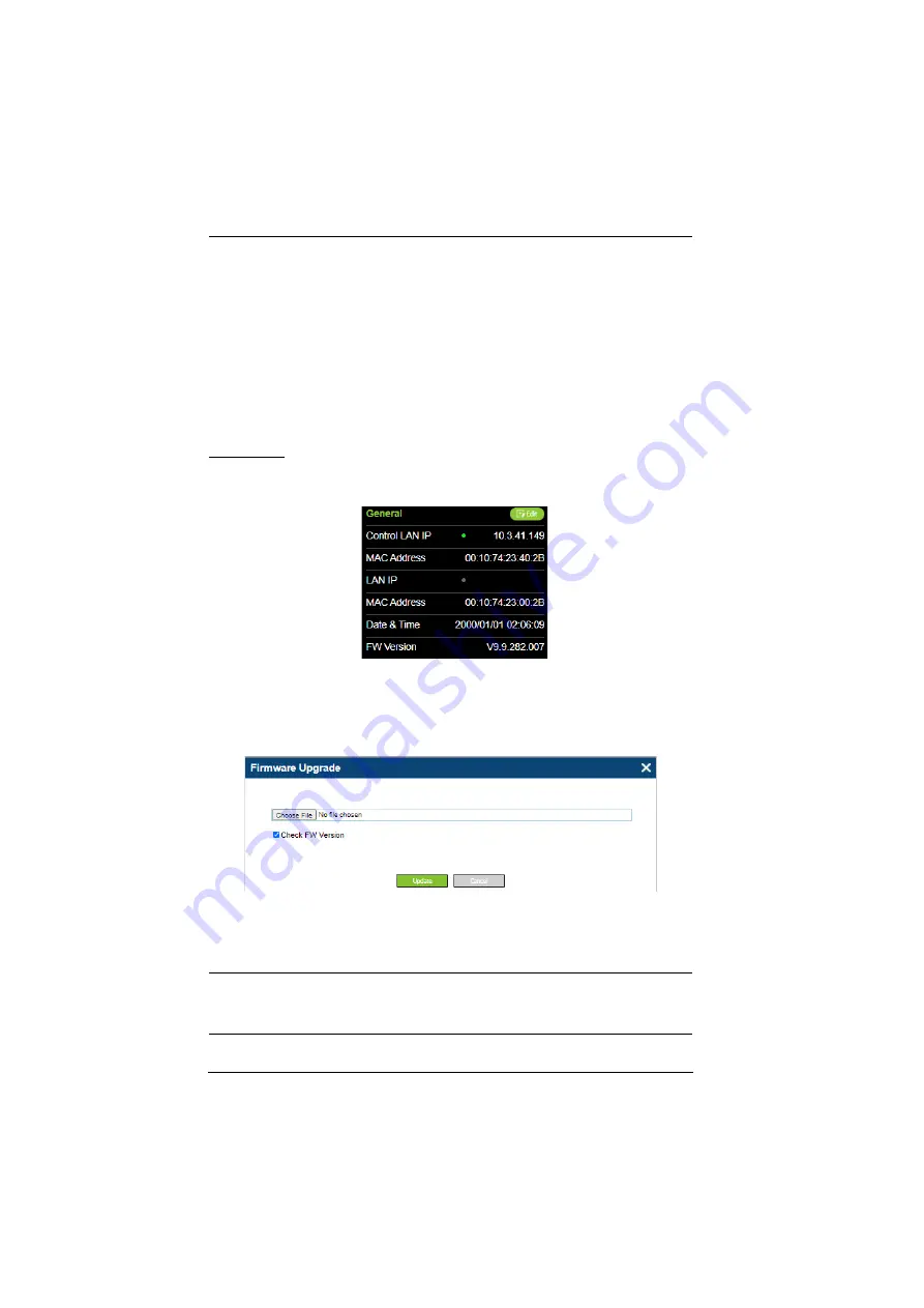
Firmware

The current firmware version of the Control Box is displayed on its web 
interface main page, as shown below.

Upgrading Firmware

To upgrade the Control Box’s firmware, download the latest firmware file from 
its product web page, and save it on the PC.

On the Control Box’s web interface main page, click 

Edit

 next to 

General

, and 

click 

Update

 under 

Firmware

. Then browse for the downloaded firmware file 

to upgrade.

Note:

When 

Check FW Version

 is checked, the unit will compare its current 

firmware version with that of the firmware file selected, and only allow 
upgrading to a later version.

Summary of Contents for VK1100A

Page 1: ...ATEN Control System User Manual www aten com VK1100A VK1200 VK2100A VK2200 Control Box Gen 2 Setup Guide ...

Page 2: ...a is likely to cause harmful interference in which case the user will be required to correct the interference at his own expense The device complies with Part 15 of the FCC Rules Operation is subject to the following two conditions 1 this device may not cause harmful interference and 2 this device must accept any interference received including interference that may cause undesired operation FCC C...

Page 3: ... VK1200 6 VK2200 7 2 Getting Started Overall Installation Procedure 9 Placement 10 Rack Mount 10 VK2100A VK2200 10 VK1100A VK1200 11 Desktop 13 Powering the Control Box 13 Terminology Description Control Box Control Box Gen 2 Control Box or Control Box Gen 2 refers to ATEN Control Box Gen 2 models including VK1100A VK1200 VK2100A and VK2200 controller Controller refers to all models of ATEN Contro...

Page 4: ...e 17 Licenses 18 Adding Licenses 18 4 Wiring Wiring and Connecting to Devices 19 12 V DC Power Output 19 Independent Power Supply 20 Relay 21 Using Self Supplied Power 21 Digital I O 23 Digital Input 23 Digital Output 24 Bidirectional Serial 26 RS 232 3 Pin 26 RS 232 422 485 5 Pin 27 Unidirectional IR Serial 27 IR Connection 28 Serial Connection 28 Control LAN 29 5 ATEN Configurator ATEN Configura...

Page 5: ...lly connected users will be able to configure all in room devices using the ATEN Configurator software VK6000 and allow remote control using ATEN Touch Panel ATEN Keypads and Android iOS Windows mobile devices via the ATEN Control System app For a centralized management the VK1200 VK2200 can be connected to ATEN Unizon a global AV management platform software allowing users to control and monitor ...

Page 6: ...ompatible Products on the product web page for details Consider the recommended maximum length of each interface cable as listed below and choose an appropriate installation location for the Control Box Note The maximum allowed length of each interface cable may vary de pending on the cable quality Interface VK1100A VK1200 VK2100A VK2200 Bidirectional RS232 422 485 Serial 3 Pin RS 232 1 4 6 5 Pin ...

Page 7: ...s of Control Box Gen 2 and run VK6000 Windows 7 8 8 1 10 Installed with Net Framework V4 5 or later Take note of the network information and login credentials of each IP device that will be connecting to and managed by the Control Box if any Front Panel VK1100A VK1200 1 2 3 4 6 5 8 9 10 11 12 14 1 2 3 5 7 8 9 4 10 14 13 11 ...

Page 8: ...cessful connection to the network 6 System LED Blinks green to indicate that the system is running without issues 7 Control LAN LED Lights green to indicate successful connection to the network 8 DC output overload LED Lights orange to indicate DC output exceeding the maximum output threshold with the buzzer beeping for 3 seconds Note Please unplug any of the connected devices to keep its total ou...

Page 9: ...ers are being uploaded and lights green to indicate a successful upload with the buzzer beeping once upon USB plug in and once upon upload success The LED lights orange to indicate upload failure with the buzzer beeping 3 times for no available file found or upload failure 11 reset button Clear all settings but network Press and hold until the front panel LEDs blink once with the buzzer beeping on...

Page 10: ...Overview 6 Rear Panel VK1100A VK1200 VK2100A 1 2 3 4 5 10 6 7 8 9 1 2 3 4 5 10 6 9 7 8 11 1 3 4 5 6 7 8 10 9 2 ...

Page 11: ...igital Input VDC Mode 0 24 V DC programmable range of 1 24 V DC Dry Contact Mode Pull up 2k Ω to 12 V DC Digital Output 300 mA sink from 24 V DC 6 IR serial ports 2 4 8 IR ports that can also be configured as RS 232 TX ports pin 1 Signal pin 2 Ground 7 RS 232 422 485 serial ports 1 2 5 pin RS 232 422 485 serial ports by pin assignment 8 RS 232 serial ports 1 4 6 3 pin RS 232 serial ports with Tx R...

Page 12: ...ices and configuration by the ATEN Configurator VK6000 as well as for remote control by ATEN Keypads Touch Panel or the ATEN Control System app on mobile devices Default network settings when no dynamic IP address is assigned by a DHCP server after 30 seconds IP 192 168 0 60 mask 255 255 255 0 No Component Description ...

Page 13: ...nting the Control Box see Placement page 10 Step 2 Powering the Control Box see Powering the Control Box page 13 Step 3 ID Setting and Initialization see ID Network License Configuration page 14 Step 4 Wiring and Connecting Devices see Wiring and Connecting to Devices page 19 Step 5 Adding the Control Box on VK6000 see ATEN Configurator VK6000 page 30 ...

Page 14: ... system rack VK2100A VK2200 1 Using the rack mount kit attach the 2 mounting brackets onto the sides of the unit with the 6 screws M3x6 included 2 Align the mounting brackets screw holes with that of the front of the rack and secure the unit onto the rack using 4 self supplied screws ...

Page 15: ...ust be purchased separately 2X 049G single rack mount 1 Using the rack mount kit attach the 2 mounting brackets onto the sides of the unit with the 4 screws M3x6 included 2 Align the mounting brackets screw holes with that of the front of the rack and secure the unit onto the rack using 2 self supplied screws ...

Page 16: ...e 4 of the screws from step 2 to secure the two VK1100A VK1200 units together with the link bracket Then install the left and right mounting brackets onto the sides of the units using 2 of the M3x5 and M3x6 screws included 3 Align the mounting brackets screw holes with that of the front of the rack and secure the units onto the rack using 4 self supplied screw ...

Page 17: ...tricity 2 Plug the power cord into the unit s power socket No 1 Rear Panel page 6 and connect it to an AC power source 3 Using a self supplied Cat 5e 6 cable connect the unit to a secured subnetwork via Control LAN port for VK1200 VK2200 No 11 Rear Panel page 6 LAN port for VK1100A VK2100A No 10 Rear Panel page 6 4 Optional For VK1200 2200 use another Cat 5e 6 cable to connect the unit to the corp...

Page 18: ...n of the VK1200 VK2200 can be found on its LCD panel via Information as illustrated below VK1100A VK2100A VK1200 VK2200 DHCP When connected to a DHCP network the control box is assigned with an IP address automatically upon startup Non DHCP When no dynamic IP address is assigned to it within 30 seconds after startup the control box s default network settings are applied LAN Default IP Address 192 ...

Page 19: ...P Installer 1 Using a Windows PC download the IP Installer zip file in Support and Downloads from the ATEN controller s product web page 2 Extract and execute IPInstaller exe A window similar to the one below appears 3 Make sure the proper network adapter is selected and click Enumerate to search for and display your ATEN controllers within the Device List ...

Page 20: ...tings to change its IP address subnet mask and default gateway Web Interface Accessing the Web Interface 1 Open a web browser enter the Control Box s IP address and log into its web interface using the default access key password Upon login the user will be prompted and required to set a new password for the unit 2 Click Settings Network select Manually DHCP off from the Get IP Address drop down l...

Page 21: ...e IP device it is previously assigned to has been inactive for Firmware The current firmware version of the Control Box is displayed on its web interface main page as shown below Upgrading Firmware To upgrade the Control Box s firmware download the latest firmware file from its product web page and save it on the PC On the Control Box s web interface main page click Edit next to General and click ...

Page 22: ... default the Control Box is supplied with 2 free licenses for granting remote control to 2 mobile devices To add additional licenses click Edit next to Licenses on its web interface main page and click Add License Then follow the on screen instructions to export a license file apply for a license upgrade and import the upgraded license file License VK1100A VK2100A VK1200 VK2200 Free Licenses 2 2 M...

Page 23: ...rectional IR Serial page 27 Control LAN see Control LAN page 29 Note All diagrams herein are exemplified using VK2200 12 V DC Power Output The Control Box Gen 2 provides the following 12 V DC output s It can power one or four independent hardware device s as illustrated below as well as relay or digital output devices Note For powering relay or digital output devices connected please refer to Powe...

Page 24: ...g the channel s off To correct power overload 1 Turn off the Control Box 2 Disconnect all devices connected to the 12 V DC outputs 3 Turn the Control Box back on 4 Reconnect the devices one at a time to ensure the maximum current threshold is not exceeded Power Supply 12 V DC 1 A 2 A Max Provides 12 V DC power to independent hardware devices Connects to 12 V DC Output Ports ...

Page 25: ...Supplied Power VK1100A VK1200 VK2100A VK2200 Number of Channels 4 8 Contact Rating 24 V DC 2 A Default Status Normally Open Normally Open Closed Normally Open Isolated Relays Contact Rating 24 V DC 2 A Max Switch Screen Projector Lift Lighting Motorized Equipment Motion Device etc Connects to Relay Channels ...

Page 26: ...wered by 12 V DC Power Output Connects to Provides 12 V DC power for the relay loop Power Supply 12 V DC 1 A 2 A Max 12 V DC Output Ports Switch Screen Projector Lift Lighting Motorized Equipment Motion Device etc ...

Page 27: ... voltage signals 1 24 V to the Control Box to trigger certain events and or functions when the voltage signals are above or below the defined threshold VK1100A VK1200 VK2100A VK2200 Number of Channels 2 4 8 Digital Input VDC Mode Voltage range 0 24 V DC Programmable range 1 24 V DC Dry Contact Mode Pull up 2 kΩ to 12 V DC Digital Output Normally Open 300 mA sink from 24 V DC Connects to Programmab...

Page 28: ...12 V DC Power Output Digital Output Switch Screen Projector Lift Lighting and Equipment Control Connects to Programmable Digital Output Channels Digital Output 300 mA sink from 24 V DC Relay Module Power Supply 12 V DC 1 A 2 A Max Connects to Switch Screen Projector Lift Lighting and Equipment Control 12 V DC Output Ports Provides 12 V DC power for the digital output loop ...

Page 29: ...Guide 25 Digital Output Dual Power Supply Power Supply 12 V DC 1 A 2 A Max 12 V DC Output Ports Provides 12 V DC power for the digital output loop Provides connection to digital output 2 Provides connection to digital output 1 ...

Page 30: ...erminals must be wired on both the Control Box and the device connecting VK1100A VK1200 VK2100A VK2200 Number of Channels 3 Pin RS 232 1 4 6 5 Pin RS 232 422 485 1 2 2 Baud rate 300 115200 default 9600 Data bit 7 8 default Stop bit 1 default 2 Parity None default Even Odd Projector Matrix Switch Camera etc Baud Rate 300 to 115200 default 9600 Data Bit 8 default or 7 Stop Bit 1 default or 2 Parity ...

Page 31: ...2 provides the following IR serial RS 232 ports VK1100A VK1200 VK2100A VK2200 2 Pin IR Serial 2 4 8 IR Carrier Frequency 10 455 kHz Default Level Low Serial RS 232 Baud rate 300 115200 default 9600 Data bit 7 8 default Stop bit 1 default 2 Parity None default Even Odd Signal Level TTL 0 5 V DC Projector Matrix Switch Camera etc Connects to Configurable by pin assignment Bidirectional RS 232 422 48...

Page 32: ...erial Connection Connect a serial device s receiver RX and ground GND terminals to a set of serial TX and ground GND terminals of the Control Box Unidirectional TTL Level 0 5 V Baud Rate 300 to 115200 default 9600 Data Bit 8 default or 7 Stop Bit 1 default or 2 Parity None default Even or Odd IR Blu ray DVD Player TV Audio Receiver Projector etc RS 232 Camera Projector Switch Audio Mixer Multimedi...

Page 33: ... same subnetwork Control LAN VK224 VK236 VK248 VK258 Expansion Box SELECT PDU CURRENT OUTLET CURRENT IP ADDRESS SENSOR 1 SENSOR 2 OUTLET STATUS ONVIF TCP PJLink Telnet Telnet The RJ 45 port is used to connect to and access TCP UDP PJLink ONVIF HTTP HTTPS and Telnet devices The VK1200 2200 can operate as an DHCP server for assigning IP addresses to the devices eco PDU Modular Matrix Switch Ethernet...

Page 34: ...for easy remote control to all devices via ATEN Keypads Touch Panel or Control System app with mobile devices For detailed information on VK6000 as well as Control System mobile app please refer to the Control System User Manual ATEN Expansion Box For adding additional ports users can purchase the ATEN Expansion Boxes to be connected to the Control Box for flexible scalability including Copyright ...

Reviews: