Installation and Operation Manual
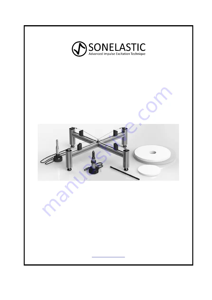
SX-PD
Adjustable support for discs and rings
ATCP Physical Engineering, Sonelastic
Division
Lêda Vassimon, 735-A - Ribeirão Preto - Brazil - 14026-567
Telephone: +55 (16) 3289-9481
www.sonelastic.com
Page 1: ...on and Operation Manual SX PD Adjustable support for discs and rings ATCP Physical Engineering Sonelastic Division Lêda Vassimon 735 A Ribeirão Preto Brazil 14026 567 Telephone 55 16 3289 9481 www sonelastic com ...
Page 2: ...table support for discs and rings Manufactured by ATCP do Brasil Alves Teodoro Cerâmicas Piezoelétricas do Brasil Ltda ATCP Physical Engineering Sonelastic Division Rua Lêda Vassimon 735 A Ribeirão Preto SP Brazil CEP 14026 567 CNPJ 03 970 289 0001 60 Inscrição estadual 797 013 492 110 Brazilian Industry www sonelastic com ...
Page 3: ...djustable support for discs and rings Page 3 of 21 Copyright Copyright 2010 2022 ATCP Physical Engineering All rights reserved ATCP reserves the right to change the product or this manual without notice Version 3 0 January 2022 ...
Page 4: ...ion 11 8 1 Requirements 11 8 2 Typical arrangements 11 8 3 Replacing the support cables 13 8 4 Mounting the acoustic sensor in the vertical base 14 8 5 Installing the IED Automatic Impulse Device 15 9 Support operation 16 9 1 Positioning the specimen 16 9 2 Positioning the acoustic sensor 16 9 3 Positioning the IED Automatic Impulse Device 17 10 Acquisition and excitation modes 18 11 Warnings and ...
Page 5: ...lus Elastic modulus or Young s modulus is defined as the slope of the stress strain curve at the elastic region as described by Hooke s Law The elastic modulus determined by Impulse Excitation Technique is also termed as dynamic elastic modulus Damping Damping is the phenomenon by which mechanical energy is dissipated in dynamic systems It is directly linked to the presence of defects and to the m...
Page 6: ...cessories and optional items SX PD Support is available in both manual and automatic configurations Optional items are offered to customize the Sonelastic Systems Manual configuration Parts 01 SX PD Support 02 CA PD Acoustic Sensor with vertical mounting base Accessories 03 Medium Manual Impulse Device ...
Page 7: ...d rings Page 7 of 21 Automatic configuration Parts 01 SX PD Support 02 CA PD Acoustic Sensor with vertical base Accessories 03 Medium Manual Impulse Device 04 IED Automatic Impulse Device Medium RT Impulse Device 05 IED Automatic Impulse Device Control unit ...
Page 8: ... 01 Support cables tensioning spring 02 Support cable 03 Central anchor 04 Support cable fastener 05 Large bearing bar 06 Sliding prop 07 Small bearing bar 08 Leveling feet 09 Vertical bearing bar CA PD Acoustic Sensor 01 Sensor 02 P2 plug 3 5 mm 03 Flexible cable 04 Cable gland 05 Frame 06 Vertical mounting base ...
Page 9: ...7 Specimens 7 1 Recommended aspect ratios Minimum aspect ratios must be observed to avoid coupling between specimen s vibration modes In addition aspect ratio determines the pattern of frequency spectrum of the acoustic response We advise users to standardize the aspect ratio in order to facilitate the frequencies identification The table below presents the recommended aspect ratio and typical dim...
Page 10: ...ction of aspect ratio and material Young s modulus the frequency should be lower than CA DP Acoustic Sensor maximum frequency 96 kHz It is possible to estimate the frequency using Sonelastic Software simulation tool The higher the Youngs modulus the higher the frequency 7 2 Placing the specimen The specimen should be symmetrically placed on the support cables and only by its edges Typical placemen...
Page 11: ...g is needed to power the computer up The support installation consists of positioning it over the workbench coupling the acoustic CA DP Acoustic Sensor to the vertical base and connecting it to the acquisition card 8 2 Typical arrangements Next are presented the typical arrangements for SX PD Support 1 Configuration Manual Specimen Disc Acoustic sensor Using a vertical mounting base Impulse device...
Page 12: ...pulse Device with Medium RT Impulse Device for IED 4 Configuration Automatic Specimen Ring Acoustic sensor Using a vertical mounting base Impulse device IED Automatic Impulse Device with Medium RT Impulse Device for IED 5 Configuration Manual Specimen Rectangular plate Acoustic sensor Using a vertical mounting base Impulse device IED Automatic Impulse Device with Medium RT Impulse Device for IED ...
Page 13: ...ension applied on them Step 02 Slide the sliding props to the center of the support to free up space near the tensioning springs Step 03 Using pliers firmly secure the ends of the support cable and pull to detach it from the tensioning spring lug Step 04 Release the other support cable end of its tensioning spring lug then the cable will free from the support Step 05 Repeat the previous steps if i...
Page 14: ...nsuring the wire goes out through the side opening as shown below Step 02 Press the base against the acoustic sensor until it feels coupled and secured to the base Step 03 Position the acoustic sensor under the specimen near its edges allowing a distance of approximately 1 cm between the specimen face and the acoustic sensor as shown next Step 04 Connect the acoustic sensor to the acquisition card...
Page 15: ...tep 01 Place the RT Impulse Device below the specimen near the edge diametrically opposite to the acoustic sensor Adjust the distance between the impact tip and the specimen surface to approximately 1 cm as shown next Step 02 Connect the RT Impulse Device cable to the output jack at the IED Automatic Impulse Device control unit ...
Page 16: ...3 Place the specimen on the support cables and using a ruler centralize the sliding props and the specimen with respect the support After completing these steps the specimen will be read for characterization Attention Respect the maximum and minimum dimensions as describe in 6 Specifications 9 2 Positioning the acoustic sensor Step 01 Mount the acoustic sensor on the vertical mounting base as desc...
Page 17: ...ll the RT Impulse Device as described in 8 5 Installing the IED Automatic Impulse Device Step 02 Turn the impulse device adjusting nut anti clockwise so the tip of the device moves and stays at approximately 3 mm away from the specimen s face Step 03 To configure the Impulse Device intensity verify the IED Installation and Operation Manual ...
Page 18: ...sed to characterize the resonance frequencies of rectangular plates too however the equipment is not able to calculate elastic moduli for this geometry 11 Warnings and support transportation Reading all the information contained in this Installation and Operation Manual is compulsory for the correct use of the support The electricity network where the optional items and accessories will be connect...
Page 19: ...the weight limits specified by the manufactures Specimen does not fit between the sliding props The dimensions of the specimen are above the specified limits Verify 8 Specifications to verify the maximum dimensions specified by the manufactures 13 Symbology Attention Risk of danger 14 Technical support and warranty If the support presents any abnormality verify if the problem is listed in 12 Maint...
Page 20: ...able support for discs and rings Page 20 of 21 15 Statement of responsibility ATCP Physical Engineering takes total technical and legal responsibility over the SX PD Support and guarantees that all information here provided are true ...
Page 21: ...Sonelastic Systems SX PD Adjustable support for discs and rings Page 21 of 21 Notes ...