Installation and Operations Manual
AT&T Proprietary (Internal Use Only)
—34—
5 System Installation
During the installation process, initially the DLT determines where to install the DLC
cabinet. The DLT will measure AT&T Cellular Data Service signal strength at various
locations in the home using an application installed on their wireless tablet device. The DLT
will take into consideration AT&T Cellular Data Service strength measurements when
determining where to install the cabinet. An AC power outlet must be in the proximity of the
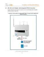
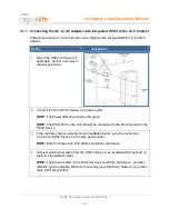
DLC. After identifying the DLC installation location, the DLT will install the DLC AC-to-AC
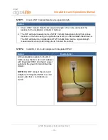
Adapter with Integrated HPAV functionality at the planned location.
NOTE:
DO NOT connect the DLC Cabinet to an AC power outlet that is controlled by a
switch.
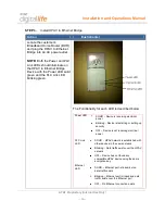
Next, the DLT will go to the location of the customer’s Broadband Home Router (BHR) and
install a HomePlug AV (HPAV) to Ethernet Bridge and establish an Ethernet connection
with the BHR using a Cat5 cable. The DLT will verify that there is a HPAV network
connection between the HPAV to Ethernet Bridge at the customer’s BHR and the DLC AC-
to-AC Adapter with Integrated HPAV at the planned location of the installation of the DLC
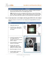
Cabinet. Afterwards, the DLT will return to the planned location for the installation of the
DLC Cabinet and proceed with the installation of the cabinet. This step includes terminating
the power and data cabling on the adapter and in the DLC cabinet.
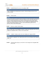
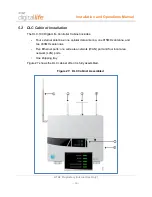
In summary, there are the nine (9) steps for installing the DLC Cabinet:
1. Check AT&T Cellular Data Service signal strength
2. Install DLC AC-to-AC Adapter with Integrated HPAV at location of DLC Cabinet
3. Install HPAV to Ethernet Bridge at the customer’s BHR
4. Observe LEDs
5. Establish Ethernet Connection to Customer’s BHR
6. Observe LEDs
7. Return to Location of DLC Cabinet
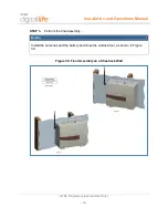
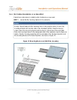
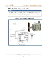
8. Install the DLC
9. Terminate data and power on the DLC AC-to-AC Adapter with Integrated HPAV and
the DLC


