


1-14
Chapter 1: Product introduction
Chapter 1
1.2.8
Onboard LEDs
2.
DRAM LED
DRAM LED checks the DRAM in sequence during motherboard booting process. If an
error is found , the LED next to the error device will continue lighting until the problem
is solved. This user-friendly design provides an intuitional way to locate the root
problem within a second.
3.
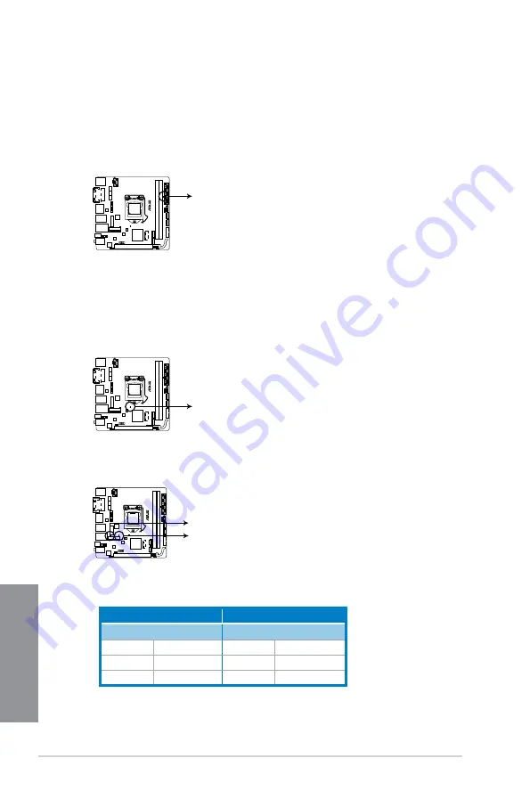
Bluetooth LED and WiFi module LED
1.
Standby Power LED
The motherboard comes with a standby power LED that lights up to indicate that the
system is ON, in sleep mode, or in soft-off mode. This is a reminder that you should
shut down the system and unplug the power cable before removing or plugging in any
motherboard component. The illustration below shows the location of the onboard LED.
Z97I-PLUS
SB_PWR
Z97I-PLUS Standby power LED
Z97I-PLUS
DRAM_LED
Z97I-PLUS DRAM LED
Z97I-PLUS
BT_LED
WIFI_LED
Z97I-PLUS Bluetooth LED
* Bluetooth and Wi-Fi module LED indications
Wi-Fi LED
Bluetooth LED
Status
Description
Status
Description
Off
No link
Off
No link
Green
Linked
Blue
Linked
Blinking
Data activity
* Wi-Fi 802.11 a/b/g/n/ac, Bluetooth v4.0
** The Bluetooth word mark and logos are owned by Bluetooth SIG, Inc. and any use of such mark by ASUSTeK
Computer Inc. is under license. Other trademarks and trade names are those of their respective owners.
Summary of Contents for Z97I-PLUS
Page 1: ...Motherboard Z97I PLUS ...
Page 41: ...ASUS Z97I PLUS 2 7 Chapter 2 To uninstall the CPU heatsink and fan assembly ...
Page 42: ...2 8 Chapter 2 Basic installation Chapter 2 2 1 4 DIMM installation To remove a DIMM ...
Page 43: ...ASUS Z97I PLUS 2 9 Chapter 2 2 1 5 ATX Power connection OR OR ...
Page 44: ...2 10 Chapter 2 Basic installation Chapter 2 2 1 6 SATA device connection OR ...