background image

1-2

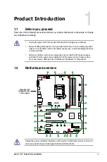
Chapter 1: Product Introduction

1.2.1 

Layout contents

Connectors/Jumpers/Slots

Page

1. 

ATX power connectors (24-pin EATXPWR, 8-pin EATX12V) 

1-2

2. Intel

®

 LGA1151 CPU socket

1-3

3.

CPU, chassis, and AIO pump fan connectors (4-pin CPU_FAN, 4-pin CHA_FAN1~2, 

4-pin AIO_PUMP FAN) 

1-3

4. DDR4 DIMM slots

1-3

5. USB 3.1 Gen 1 connector (20-1 pin U31G1_56)

1-3

6. M.2 sockets (M.2_1; M.2_2)

1-4

7. Intel

®

 B360 Serial ATA 6.0 Gb/s connector (7-pin SATA6G_1~6)

1-4

8. System panel connector (20-3 pin PANEL)

1-4

9.

Clear RTC RAM (2-pin CLRTC)

1-5

10. USB 2.0 connector (10-1 pin USB1114)

1-5

11.

AURA RGB header (4-pin RGB_HEADER)

1-5

12.

Serial port connector (10-1 pin COM)

1-5

13.

Front panel audio connector (10-1 pin AAFP)

1-6

14. Digital audio connector (4-1 pin SPDIF_OUT)

1-6

15. PCI Express 3.0/2.0 x1 slots

1-6

16. PCI Express 3.0/2.0 x16 slots

1-6

ATX power connectors (24-pin EATXPWR, 8-pin EATX12V) 

Correctly orient the ATX power supply plugs into these 

connectors and push down firmly until the connectors 

completely fit.

EATX12V

+12V DC

+12V DC

+12V DC

+12V DC

GND

GND

GND

GND

EATXPWR

PIN 1

PIN 1

GND

+5 Volts

+5 Volts

+5 Volts

-5 Volts

GND

GND

GND

PSON#

GND

-12 Volts

+3 Volts


+3 Volts

+12 Volts

+12 Volts

+5V Standby

Power OK

GND

+5 Volts

GND

+5 Volts

GND

+3 Volts

+3 Volts


• 

For a fully configured system, we recommend that you use a power supply unit 

(PSU) that complies with ATX 12 V Specification 2.0 (or later version) and provides 

a minimum power of 350 W. This PSU type has 24-pin and 8-pin power plugs.

• 

We recommend that you use a PSU with higher power output when configuring a 

system with more power-consuming devices or when you intend to install additional 

devices. The system may become unstable or may not boot up if the power is 

inadequate.

Summary of Contents for TUF B360-PRO GAMING

Page 1: ...Motherboard TUF B360 PRO GAMING ...

Page 2: ... respective companies and are used only for identification or explanation and to the owners benefit without intent to infringe Offer to Provide Source Code of Certain Software This product contains copyrighted software that is licensed under the General Public License GPL under the Lesser General Public License Version LGPL and or other Free Open Source Software Licenses Such software in this prod...

Page 3: ...ecifications summary vi Chapter 1 Product Introduction 1 1 Before you proceed 1 1 1 2 Motherboard overview 1 1 1 3 Central Processing Unit CPU 1 9 1 4 System memory 1 10 Chapter 2 BIOS Information 2 1 Managing and updating your BIOS 2 1 2 2 BIOS setup program 2 6 2 3 Exit menu 2 11 Appendix Notices A 1 ...

Page 4: ...on safety Before installing the motherboard and adding devices on it carefully read all the manuals that came with the package Before using the product ensure all cables are correctly connected and the power cables are not damaged If you detect any damage contact your dealer immediately To avoid short circuits keep paper clips screws and staples away from connectors slots sockets and circuitry Avo...

Page 5: ... of the following symbols used throughout this manual DANGER WARNING Information to prevent injury to yourself when trying to complete a task CAUTION Information to prevent damage to the components when trying to complete a task IMPORTANT Instructions that you MUST follow to complete a task NOTE Tips and additional information to help you complete a task Typography Bold text Indicates a menu or an...

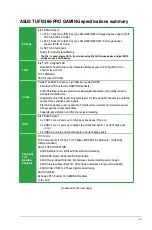
Page 6: ...el B360 Chipset Memory 4 x DIMM max 64GB DDR4 2666 2400 2133 MHz non ECC un buffered memory Dual channel memory architecture Supports Intel Extreme Memory Profile XMP DDR4 2666 MHz and higher memory modules will run at max 2666 MHz on Intel 8th Gen 6 core or higher processors Refer to www asus com for the latest Memory QVL Qualified Vendors List Expansion slots 1 x PCIe 3 0 2 0 x16 slot 1 x PCIe 3...

Page 7: ...udio PCB layers Separate layers for left and right channels to guard the quality of the sensitive audio signals Premium Japanese audio capacitors Provide warm natural and immersive sound with exceptional clarity and fidelity Supports jack detection and front panel jack retasking USB Intel B360 Chipset 2 x USB 3 1 Gen 2 ports up to 10Gbps at back panel Type A 3 x USB 3 1 Gen 1 ports up to 5Gbps 2 p...

Page 8: ... EZ DIY EZ Update UEFI BIOS EZ Mode Featuring friendly graphics user interface ASUS CrashFree BIOS 3 ASUS EZ Flash 3 File Transfer Cloud GO File Transfer Q Design ASUS Q LED CPU DRAM VGA Boot Device LED ASUS Q Slot ASUS Q DIMM ASUS Quiet Thermal Solution ASUS Fan Xpert 4 Core Stylish Fanless Design PCH Heat sink MOS Heat sink Back Panel I O Ports 1 x D sub port 1 x HDMI port 1 x PS 2 combo port 1 ...

Page 9: ...udio connector AAFP 1 x 24 pin EATX Power connector 1 x 8 pin EATX 12V Power connector 1 x System Panel 1 x COM port 1 x S PDIF header 1 x RGB header 1 x Clear CMOS jumper BIOS 128 Mb Flash ROM UEFI AMI BIOS PnP DMI3 0 WfM2 0 SM BIOS 3 1 ACPI 6 1 Multi language BIOS ASUS EZ Flash 3 CrashFree BIOS 3 F6 Qfan Control F3 My Favorites F4 AURA ON OFF F9 Search Last Modified log F12 PrintScreen and ASUS ...

Page 10: ...x ...

Page 11: ...ject such as the power supply case to avoid damaging them due to static electricity Before you install or remove any component ensure that the ATX power supply is switched off or the power cord is detached from the power supply Failure to do so may cause severe damage to the motherboard peripherals or components 1 2 Motherboard overview Unplug the power cord before installing or removing the mothe...

Page 12: ...press 3 0 2 0 x1 slots 1 6 16 PCI Express 3 0 2 0 x16 slots 1 6 ATX power connectors 24 pin EATXPWR 8 pin EATX12V Correctly orient the ATX power supply plugs into these connectors and push down firmly until the connectors completely fit EATX12V 12V DC 12V DC 12V DC 12V DC GND GND GND GND EATXPWR PIN 1 PIN 1 GND 5 Volts 5 Volts 5 Volts 5 Volts GND GND GND PSON GND 12 Volts 3 Volts 3 Volts 12 Volts ...

Page 13: ...CHA FAN IN CHA FAN PWR GND CHA_FAN2 GND CHA FAN PWR CHA FAN IN CHA FAN PWM AIO_PUMP FAN DDR4 DIMM slots Install 2 GB 4 GB 8 GB and 16 GB unbuffered non ECC DDR4 DIMMs into these DIMM sockets For more details refer to 1 4 System memory USB 3 1 Gen 1 connector 20 1 pin U31G1_56 Connect a USB 3 1 Gen 1 module to any of these connectors for additional USB 3 1 Gen 1 front or rear panel ports These conn...

Page 14: ...rial ATA 6 0 Gb s signal cables GND RSATA_TXP RSATA_TXN GND RSATA_RXN RSATA_RXP GND SATA6G System panel connector 20 3 pin PANEL This connector supports several chassis mounted functions System power LED 4 pin PWR_LED This 4 pin connector is for the system power LED Connect the chassis power LED cable to this connector The system power LED lights up when you turn on the system power and blinks whe...

Page 15: ...a CLRTC 3V_BAT GND PIN 1 If the steps above do not help remove the onboard battery and short the two pins again to clear the CMOS RTC RAM data After clearing the CMOS reinstall the battery USB 2 0 connector 10 1 pin USB1114 Connect a USB module cable to this connector then install the module to a slot opening at the back of the system chassis This USB connectors comply with USB 2 0 specifications ...

Page 16: ...ctor AAFP AGND NC SENSE1_RETUR SENSE2_RETUR PORT1 L PORT1 R PORT2 R SENSE_SEND PORT2 L HD audio compliant pin definition Digital audio connector 4 1 pin SPDIF_OUT This connector is for an additional Sony Philips Digital Interface S PDIF port Connect the S PDIF Out module cable to this connector then install the module to a slot opening at the back of the system chassis SPDIF_OUT 5V SPDIFOUT GND We...

Page 17: ...port allows Gigabit connection to a Local Area Network LAN through a network hub LAN port LED indications 1 2 2 Rear panel connectors Activity Link LED Speed LED Status Description Status Description Off No link OFF 10Mbps connection Orange Linked ORANGE 100Mbps connection Orange Blinking Data activity GREEN 1Gbps connection Orange Blinking then steady Ready to wake Wake up from S5 mode SPEED LED ...

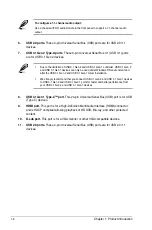
Page 18: ...vironment and after the USB 3 1 Gen 2 and USB 3 1 Gen 1 driver installation We strongly recommend that you connect USB 3 1 Gen 2 and USB 3 1 Gen 1 devices to USB 3 1 Gen 2 and USB 3 1 Gen 1 ports for faster and better performance from your USB 3 1 Gen 2 and USB 3 1 Gen 1 devices 8 USB 3 1 Gen 1 Type C port This 24 pin Universal Serial Bus USB port is for USB Type C devices 9 HDMI port This port is...

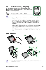
Page 19: ...the socket and the socket contacts are not bent Contact your retailer immediately if the PnP cap is missing or if you see any damage to the PnP cap socket contacts motherboard components Keep the cap after installing the motherboard ASUS will process Return Merchandise Authorization RMA requests only if the motherboard comes with the cap on the LGA1151 socket The product warranty does not cover da...

Page 20: ...at you install memory modules of the same version or date code D C from the same vendor Check with the retailer to get the correct memory modules According to Intel CPU spec DIMM voltage below 1 35V is recommended to protect the CPU Due to Intel chipset limitation DDR4 2666MHz and higher memory modules will run at max 2666MHz on Intel 8th Gen 6 core or higher processors The default memory operatio...

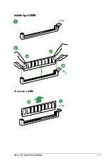
Page 21: ...ASUS TUF B360 PRO GAMING 1 11 B A A 1 2 B A Installing a DIMM To remove a DIMM ...

Page 22: ...1 12 Chapter 1 Product Introduction ...

Page 23: ...ility you can also manually update the saved BIOS and select a boot logo when the system goes into POST To launch EZ Update click EZ Update on the AI Suite 3 main menu bar BIOS Information 2 EZ Update requires an Internet connection either through a network or an ISP Internet Service Provider Model Name Z170 K version 0302 Release Date 05 22 2015 Click to automatically update your motherboard s dr...

Page 24: ...3 and press Enter to enable it 2 Follow the steps below to update the BIOS via USB or Internet Via USB a Insert the USB flash disk that contains the latest BIOS file to the USB port then select by USB b Press Tab to switch to the Drive field c Press the Up Down arrow keys to find the USB flash disk that contains the latest BIOS and then press Enter d Press Tab to switch to the Folder field e Press...

Page 25: ...m 2 Insert the support DVD to the optical drive or the USB flash drive that contains the BIOS file to the USB port 3 The utility automatically checks the devices for the BIOS file When found the utility reads the BIOS file and enters ASUS EZ Flash 3 utility automatically 4 The system requires you to enter BIOS Setup to recover BIOS settings To ensure system compatibility and stability we recommend...

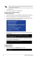
Page 26: ... select boot device ESC to boot using defaults P2 ST3808110AS 76319MB aigo miniking 250MB UEFI FAT ASUS DRW 2014L1T 4458MB P1 ASUS DRW 2014L1T 4458MB UEFI FAT aigo miniking 250MB Enter Setup 4 When the booting message appears press Enter within five 5 seconds to enter FreeDOS prompt Welcome to FreeDOS http www freedos org C d D 5 On the FreeDOS prompt type d then press Enter to switch the disk fro...

Page 27: ... Up Down or Home End keys to select the BIOS file and press Enter 4 After the BIOS Updater checks the selected BIOS file select Yes to confirm the BIOS update Are you sure you want to update the BIOS Yes No The BIOS Backup feature is not supported due to security regulations 5 Select Yes then press Enter When BIOS update is done press ESC to exit BIOS Updater 6 Restart your computer DO NOT shut do...

Page 28: ... always shut down the system properly from the operating system The BIOS setup screens shown in this section are for reference purposes only and may not exactly match what you see on your screen Visit the ASUS website at www asus com to download the latest BIOS file for this motherboard Ensure that a USB mouse is connected to your motherboard if you want to use the mouse to control the BIOS setup ...

Page 29: ... device options vary depending on the devices you installed to the system Selects the display language of the BIOS setup program Displays a quick overview of the system status Displays the system properties of the selected mode Click or to switch EZ System Tuning modes Loads optimized default settings Displays the CPU Fan s speed Click the button to manually tune the fans Enables or disables the S...

Page 30: ... following sections for the detailed configurations To access the EZ Mode click EzMode F7 or press F7 Menu items General help Menu bar Language Qfan Control F6 MyFavorite F3 AURA ON OFF F4 Search F9 Scroll bar Pop up Menu Configuration fields Last modified settings Go back to EZ Mode Hot Keys Displays a quick overview of the system status Search on the FAQ 2 8 Chapter 2 BIOS Information ...

Page 31: ...menu bar displays the current settings of your fans Use this button to manually tweak the fans to your desired settings Search F9 This button allows you to search for BIOS items by entering its name enter the item name to find the related item listing AURA F4 This button allows you to turn the RGB LED lighting or functional LED on or off ON All AURA effects will be enabled Default mode OFF All AUR...

Page 32: ... Use F12 key to capture the BIOS screen and save it to the removable storage device Configuration fields These fields show the values for the menu items If an item is user configurable you can change the value of the field opposite the item You cannot select an item that is not user configurable A configurable field is highlighted when selected To change the value of a field select it and press En...

Page 33: ...ss F10 a confirmation window appears Select OK to save changes and exit Discard Changes and Exit This option allows you to exit the Setup program without saving your changes When you select this option or if you press Esc a confirmation window appears Select OK to discard changes and exit Launch EFI Shell from USB drives This option allows you to attempt to launch the EFI Shell application shellx6...

Page 34: ...2 12 Chapter 2 BIOS Information ...

Page 35: ...adio communications However there is no guarantee that interference will not occur in a particular installation If this equipment does cause harmful interference to radio or television reception which can be determined by turning the equipment off and on the user is encouraged to try to correct the interference by one or more of the following measures Reorient or relocate the receiving antenna Inc...

Page 36: ...MB 3 B Déclaration de conformité de Innovation Sciences et Développement économique Canada ISED Le présent appareil est conforme aux CNR d Innovation Sciences et Développement économique Canada applicables aux appareils radio exempts de licence L exploitation est autorisée aux deux conditions suivantes 1 l appareil ne doit pas produire de brouillage et 2 l utilisateur de l appareil doit accepter t...

Page 37: ... from our commitment to the highest standards for protecting our environment We believe in providing solutions for you to be able to responsibly recycle our products batteries other components as well as the packaging materials Please go to http csr asus com english Takeback htm for detailed recycling information in different regions Regional notice for California WARNING Cancer and Reproductive H...

Page 38: ...соответствующим условиям соответствующих директив Подробную информацию пожалуйста смотрите на www asus com support Български С настоящото ASUSTeK Computer Inc декларира че това устройство е в съответствие със съществените изисквания и другите приложими постановления на свързаните директиви Пълният текст на декларацията за съответствие на ЕС е достъпна на адрес www asus com support Hrvatski ASUSTeK...

Page 39: ...Way Fremont CA 94539 USA Telephone 1 510 739 3777 Fax 1 510 608 4555 Web site https www asus com us Technical Support Support fax 1 812 284 0883 Telephone 1 812 282 2787 Online support https www asus com support Product ContactUs Services questionform lang en us ASUS COMPUTER GmbH Germany and Austria Address Harkort Str 21 23 40880 Ratingen Germany Fax 49 2102 959931 Web site https www asus com de...

Page 40: ...erboard Model Number TUF H370 PRO GAMING TUF B360 PRO GAMING TUF B360 PLUS GAMING Conforms to the following specifications FCC Part 15 Subpart B Unintentional Radiators Supplementary Information This device complies with part 15 of the FCC Rules Operation is subject to the following two conditions 1 This device may not cause harmful interference and 2 this device must accept any interference recei...

Reviews: