


viii
About this guide
Audience
This user guide is intended for system integrators, and experienced users with at least basic
knowledge of configuring a server.
Contents
This guide contains the following parts:
1.
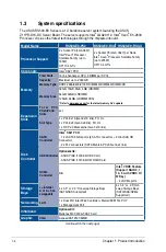
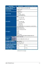
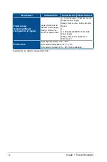
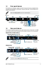
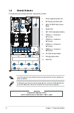
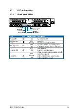
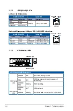
Chapter 1: Product Introduction
This chapter describes the general features of the server, including sections on front
panel and rear panel specifications.
2.
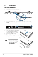
Chapter 2: Hardware Information
This chapter lists the hardware setup procedures that you have to perform when
installing or removing system components.
3.
Chapter 3: Installation Options
This chapter describes how to install optional components into the barebone server.
4.
Chapter 4: Motherboard Information
This chapter gives information about the motherboard that comes with the server. This
chapter includes the motherboard layout, jumper settings, and connector locations.
5.
Chapter 5: BIOS Setup
This chapter tells how to change system settings through the BIOS Setup menus and
describes the BIOS parameters.
6.
Chapter 6: RAID Configuration
This chapter tells how to change system settings through the BIOS Setup menus.
Detailed descriptions of the BIOS parameters are also provided.
7
Chapter 7: Driver Installation
This chapter provides instructions for installing the necessary drivers for different
system components.
Summary of Contents for RS500-E9 Series
Page 1: ...1U Rackmount Server User Guide RS500 E9 Series RS500 E9 PS4 RS500 E9 RS4 RS500 E9 RS4 U ...
Page 10: ...x ...
Page 25: ...2 5 ASUS RS500 E9 Series 6 Reinstall the air ducts CPU1 CPU socket 1 CPU2 CPU socket 2 ...
Page 51: ...3 5 ASUS RS500 E9 Series 3 2 Rail kit dimensions 589mm 43 6mm 900mm 43 6mm ...
Page 52: ...Chapter 3 Installation Options 3 6 ...
Page 54: ...Chapter 4 Motherboard Information 4 2 4 1 Motherboard layout ...
Page 148: ...6 22 Chapter 6 RAID Configuration ...
Page 155: ...7 7 ASUS RS500 E9 Series 5 Follow the onscreen instructions to complete the installation ...
Page 156: ...7 8 Chapter 7 Driver Installation ...
Page 157: ...Appendix Appendix ...
Page 158: ...Z11PR D16 DC block diagram ...