


Chapter 2: Hardware Information
2-2
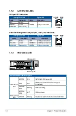
2.1
Chassis cover
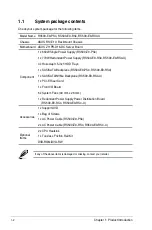
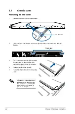
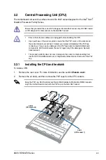
Removing the rear cover
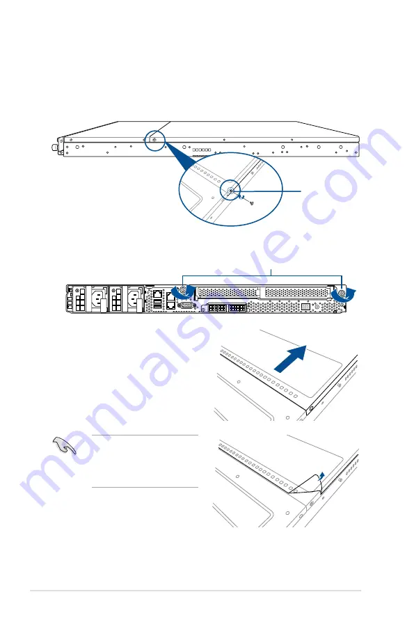
1.
Locate and remove the front side screws.
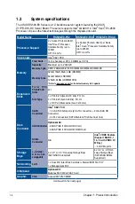
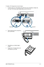
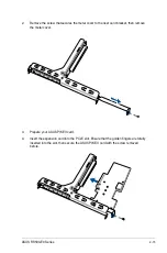
3.
Firmly hold the cover and slide it toward
the rear panel for about half an inch
until it is disengaged from the chassis.
4.
Lift the cover from the chassis.
5.
To reattach the rear cover, reverse step
1 to 4.
2.
Loosen the two thumbscrews on the rear panel to release the rear cover from the
chassis.
Thumbscrews
A protection film is pre-attached to
the system cover before shipping.
Please remove the protection film
before turning on the system for
proper heat dissipation.
Front side screw
Summary of Contents for RS500-E9 Series
Page 1: ...1U Rackmount Server User Guide RS500 E9 Series RS500 E9 PS4 RS500 E9 RS4 RS500 E9 RS4 U ...
Page 10: ...x ...
Page 25: ...2 5 ASUS RS500 E9 Series 6 Reinstall the air ducts CPU1 CPU socket 1 CPU2 CPU socket 2 ...
Page 51: ...3 5 ASUS RS500 E9 Series 3 2 Rail kit dimensions 589mm 43 6mm 900mm 43 6mm ...
Page 52: ...Chapter 3 Installation Options 3 6 ...
Page 54: ...Chapter 4 Motherboard Information 4 2 4 1 Motherboard layout ...
Page 148: ...6 22 Chapter 6 RAID Configuration ...
Page 155: ...7 7 ASUS RS500 E9 Series 5 Follow the onscreen instructions to complete the installation ...
Page 156: ...7 8 Chapter 7 Driver Installation ...
Page 157: ...Appendix Appendix ...
Page 158: ...Z11PR D16 DC block diagram ...