background image

1-13

Chapter 1: Product introduction

1.7 

System memory

1.7.1 

Overview

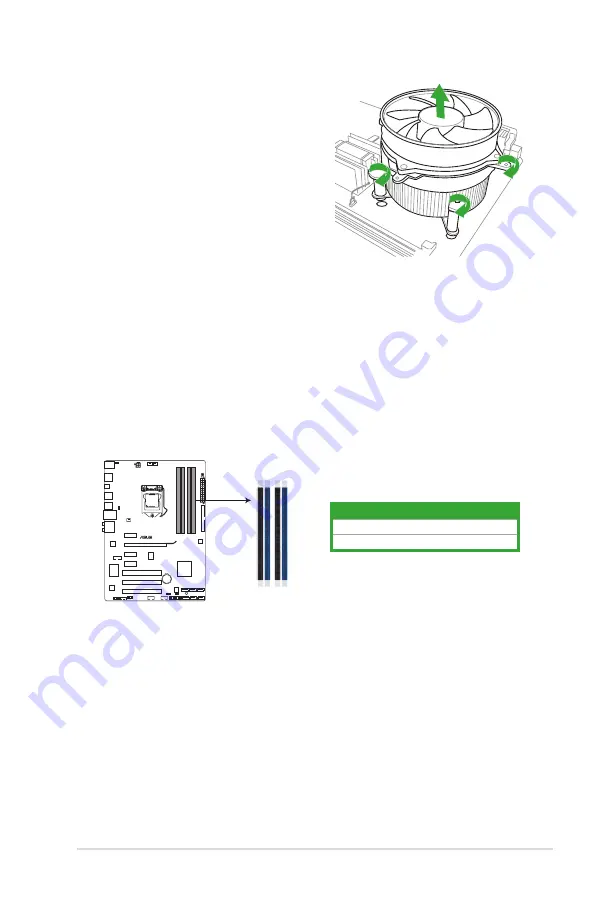
The motherboard comes with four Double Data Rate 3 (DDR3) Dual Inline Memory Modules 

(DIMM) sockets. 

A DDR3 module has the same physical dimensions as a DDR2 DIMM but is notched 

differently to prevent installation on a DDR2 DIMM socket. DDR3 modules are developed for 

better performance with less power consumption.

The figure illustrates the location of the DDR3 DIMM sockets: 

Channel

Sockets

Channel A

DIMM_A1 and DIMM_A2

Channel B

DIMM_B1 and DIMM_B2

4. 

Carefully remove the heatsink and fan 

assembly from the motherboard.

5. 

Rotate each fastener clockwise to ensure 

correct orientation when reinstalling.

P7H55

P7H55 240-pin DDR3 DIMM sockets

DIMM_A2

DIMM_A1

DIMM_B2

DIMM_B1

Summary of Contents for P7H55 series

Page 1: ...Motherboard P7H55 ...

Page 2: ...planation and to the owners benefit without intent to infringe Offer to Provide Source Code of Certain Software This product may contain copyrighted software that is licensed under the General Public License GPL and under the Lesser General Public License Version LGPL The GPL and LGPL licensed code in this product is distributed without any warranty Copies of these licenses are included in this pr...

Page 3: ...3 Motherboard layout 1 7 1 5 4 Layout contents 1 7 1 6 Central Processing Unit CPU 1 8 1 6 1 Installing the CPU 1 8 1 6 2 Installing the CPU heatsink and fan 1 11 1 6 3 Uninstalling the CPU heatsink and fan 1 12 1 7 System memory 1 13 1 7 1 Overview 1 13 1 7 2 Memory configurations 1 14 1 7 3 Installing a DIMM 1 15 1 7 4 Removing a DIMM 1 15 1 8 Expansion slots 1 16 1 8 1 Installing an expansion c...

Page 4: ...2 3 2 2 BIOS setup program 2 6 2 2 1 BIOS menu screen 2 7 2 2 2 Menu bar 2 7 2 2 3 Navigation keys 2 7 2 2 4 Menu items 2 7 2 2 5 Submenu items 2 8 2 2 6 Configuration fields 2 8 2 2 7 Pop up window 2 8 2 2 8 Scroll bar 2 8 2 2 9 General help 2 8 2 3 Main menu 2 8 2 3 1 System Time 2 9 2 3 2 System Date 2 9 2 3 3 SATA1 6 2 9 2 3 5 System Information 2 10 2 3 4 Storage Configuration 2 10 2 4 Ai Twe...

Page 5: ...Intel VT d 2 20 2 6 Power menu 2 20 2 6 1 Suspend Mode 2 21 2 6 2 ACPI 2 0 Support 2 21 2 6 3 ACPI APIC Support 2 21 2 6 4 APM Configuration 2 21 2 6 5 Hardware Monitor 2 22 2 7 Boot menu 2 23 2 7 1 Boot Device Priority 2 23 2 7 2 Boot Settings Configuration 2 24 2 7 3 Security 2 24 2 8 Tools menu 2 25 2 8 1 ASUS O C Profile 2 26 2 8 2 AI NET 2 2 26 2 8 3 ASUS EZ Flash 2 2 26 2 8 4 Express Gate 2 ...

Page 6: ...t from that to which the receiver is connected Consult the dealer or an experienced radio TV technician for help The use of shielded cables for connection of the monitor to the graphics card is required to assure compliance with FCC regulations Changes or modifications to this unit not expressly approved by the party responsible for compliance could void the user s authority to operate this equipm...

Page 7: ...peration safety Before installing the motherboard and adding devices on it carefully read all the manuals that came with the package Before using the product ensure that all cables are correctly connected and the power cables are not damaged If you detect any damage contact your dealer immediately To avoid short circuits keep paper clips screws and staples away from connectors slots sockets and ci...

Page 8: ...uct and software updates 1 ASUS websites The ASUS website provides updated information on ASUS hardware and software products Refer to the ASUS contact information 2 Optional documentation Your product package may include optional documentation such as warranty flyers that may have been added by your dealer These documents are not part of the standard package Typography Bold text Indicates a menu ...

Page 9: ...IMM per channel Refer to www asus com for the latest Memory QVL Qualified Vendors List When you install a total memory of 4GB or more Windows 32 bit operating system may only recognize less than 3GB We recommend a maximum of 3GB system memory if you are using a Windows 32 bit operating system Expansion slots 1 x PCI Express 2 0 x16 slot 3 x PCI Express 2 0 x1 slots 2 5GT s gray slots 3 x PCI slots...

Page 10: ...Core Adjustable CPU voltage at 0 00625V increment vIMC Adjustable IMC voltage at 0 05V increment vDRAM Bus 11 step DRAM voltage control vPCH 2 step chipset voltage control vCPU PLL 4 step reference voltage control SFS Stepless Frequency Selection Internal Base Clock tuning from 80 MHz up to 500 MHz at 1MHz increment PCI Express frequency tuning from 100MHz up to 200MHz at 1MHz increment Overclocki...

Page 11: ...ector 1 x System panel connector 1 x MemOK button 1 x COM connector BIOS 16 Mb Flash ROM AMI BIOS PnP DMI 2 0 WfM 2 0 SM BIOS 2 5 ACPI 2 0a Multi language BIOS ASUS EZ Flash 2 ASUS CrashFree BIOS 3 Manageability WfM 2 0 DMI 2 0 WOL by PME WOR by PME PXE Accessories 1 x Ultra DMA 133 100 cable 2 x Serial ATA 3 0Gb s cables 1 x I O shield 1 x User Manual Support DVD Drivers ASUS Utilities ASUS Updat...

Page 12: ...2 0 lanes providing great graphics performance Intel Lynnfield processor is one of the most powerful and energy efficient CPU in the world Moreover Intel and Clarkdale processor integrated Graphics Procession Unit GPU which goes with Intel H55 chipset with VGA out can bring you to he whole new experience of the next generation VGA performance It also provides separated 3D 2D and Video Engines to e...

Page 13: ...o systems via the S PDIF out SONY PHILIPS Digital Interface jack It allows digital audio transfer and keeps the best signal quality 8 channel audio CODEC Enjoy high end sound quality on your PC The onboard 8 channel High Definition Audio CODEC enables high quality 192KHz 24 bit audio output jack sensing feature and multi streaming technology Gigabit LAN solution The onboard LAN controller is a hig...

Page 14: ... USB drives It supports file downloading to USB drives only Stylish Heatsink The crystal shaped heatsink features 0 dB thermal solution that offers users a noiseless PC environment Not only the beautiful shape upgrades the visual enjoyment for motherboard users but also the heatsink design lowers the temperature of the chipset and power phase area through high efficient heat exchange Combined with...

Page 15: ...ning on the system and any faulty cable connections are reported back up to 100 meters at 1 meter accuracy C P R CPU Parameter Recall The BIOS C P R feature automatically restores the CPU default settings when the system hangs due to overclocking failure C P R eliminates the need to open the system chassis and clear the RTC data Simply shut down and reboot the system and the BIOS automatically res...

Page 16: ...omponent place it on a grounded antistatic pad or in the bag that came with the component Before you install or remove any component ensure that the ATX power supply is switched off or the power cord is detached from the power supply Failure to do so may cause severe damage to the motherboard peripherals or components Onboard LED The motherboard comes with a standby power LED that lights up to ind...

Page 17: ... and damage motherboard components 1 5 1 Placement direction When installing the motherboard ensure that you place it into the chassis in the correct orientation The edge with external ports goes to the rear part of the chassis as indicated in the image below 1 5 2 Screw holes Place six screws into the holes indicated by circles to secure the motherboard to the chassis Do not overtighten the screw...

Page 18: ...9 12 11 14 16 15 17 13 2 1 5 4 Layout contents Connectors Jumpers Slots LED Page Connectors Jumpers Slots LED Page 1 Keyboard power 3 pin KBPWR 1 18 10 Serial ATA connectors 7 pin SATA1 6 1 25 2 USB device wake up 3 pin USBPW1 8 3 pin USBPW9 12 1 18 11 Onboard LED SB_PWR 1 5 3 CPU power and chassis fan connectors 4 pin CPU_FAN 3 pin PWR_FAN 3 pin CHA_FAN 1 24 12 System panel connector 20 8 pin PAN...

Page 19: ...is shipment transit related Keep the cap after installing the motherboard ASUS will process Return Merchandise Authorization RMA requests only if the motherboard comes with the cap on the LGA1156 socket The product warranty does not cover damage to the socket contacts resulting from incorrect CPU installation removal or misplacement loss incorrect removal of the PnP cap 1 6 1 Installing the CPU To...

Page 20: ...he tab only The CPU fits in only one correct orientation DO NOT force the CPU into the socket to prevent bending the connectors on the socket and damaging the CPU Gold triangle mark Alignment keys CPU notches 5 Position the CPU over the socket ensuring that the gold triangle is on the bottom left corner of the socket and then fit the socket alignment keys into the CPU notches PnP cap Cap tab ...

Page 21: ...tab 6 Apply some Thermal Interface Material to the exposed area of the CPU that the heatsink will be in contact with ensuring that it is spread in an even thin layer Some heatsinks come with pre applied thermal paste If so skip this step The Thermal Interface Material is toxic and inedible DO NOT eat it If it gets into your eyes or touches your skin wash it off immediately and seek professional me...

Page 22: ...nsion Ensure that you have installed the motherboard to the chassis before you install the CPU fan and heatsink assembly The type of CPU heatsink and fan assembly may differ but the installation steps and functions should remain the same The illustration above is for reference only To install the CPU heatsink and fan 1 Place the heatsink on top of the installed CPU ensuring that the four fasteners...

Page 23: ...ector 1 6 3 Uninstalling the CPU heatsink and fan To uninstall the CPU heatsink and fan 1 Disconnect the CPU fan cable from the connector on the motherboard 2 Rotate each fastener counterclockwise 3 Pull up two fasteners at a time in a diagonal sequence to disengage the heatsink and fan assembly from the motherboard A A B B A A B B CPU_FAN CPU FAN PWM CPU FAN IN CPU FAN PWR GND P7H55 P7H55 CPU fan...

Page 24: ...stallation on a DDR2 DIMM socket DDR3 modules are developed for better performance with less power consumption The figure illustrates the location of the DDR3 DIMM sockets Channel Sockets Channel A DIMM_A1 and DIMM_A2 Channel B DIMM_B1 and DIMM_B2 4 Carefully remove the heatsink and fan assembly from the motherboard 5 Rotate each fastener clockwise to ensure correct orientation when reinstalling P...

Page 25: ...nded to protect the CPU According to Intel CPU spec CPUs with a core frequency of 2 66GHz support the maximum DIMM frequency of up to DDR3 1333 To use DIMMs of a higher frequency with a 2 66GHz CPU enable the DRAM O C Profile feature in BIOS Refer to section 2 4 1 Ai Overclock Tuner for details Always install DIMMs with the same CAS latency For optimum compatibility we recommend that you obtain me...

Page 26: ...all a DIMM 1 Unlock a DIMM socket by pressing the retaining clip outward 2 Align a DIMM on the socket such that the notch on the DIMM matches the DIMM slot key on the socket Support the DIMM lightly with your fingers when pressing the retaining clip The DIMM might get damaged when it flips out with extra force Ensure to unplug the power supply before adding or removing DIMMs or other system compon...

Page 27: ...cover 1 8 2 Configuring an expansion card After installing the expansion card configure it by adjusting the software settings 1 Turn on the system and change the necessary BIOS settings if any See Chapter 2 for information on BIOS setup 2 Assign an IRQ to the card 3 Install the software drivers for the expansion card When using PCI cards on shared slots ensure that the drivers support Share IRQ or...

Page 28: ...ery You do not need to clear the RTC when the system hangs due to overclocking For system failure due to overclocking use the CPU Parameter Recall C P R feature Shut down and reboot the system then the BIOS automatically resets parameter settings to default values Due to the chipset limitation AC power off is required before you use the C P R function You must turn off and on the power supply or u...

Page 29: ...eep mode CPU stopped DRAM refreshed system running in low power mode using the connected USB devices Set to 5VSB to wake up from S3 and S4 sleep modes no power to CPU DRAM in slow refresh power supply in reduced power mode The USB device wake up feature requires a power supply that can provide 500mA on the 5VSB lead for each USB port otherwise the system would not power up The total current consum...

Page 30: ...DIMMs during the tuning process the system continues memory tuning after turning on the computer To stop memory tuning turn off the computer and unplug the power cord for about 5 10 seconds If your system fail to boot due to BIOS overclocking press the MemOK switch to boot and load BIOS default settings A messgae will appear during POST reminding you that the BIOS has been restored to its default ...

Page 31: ...ort connects the center subwoofer speakers 4 Rear Speaker Out port black This port connects the rear speakers in a 4 channel 6 channel or 8 channel audio configuration 5 Line In port light blue This port connects the tape CD DVD player or other audio sources 6 Line Out port lime This port connects a headphone or a speaker In 4 channel 6 channel and 8 channel configurations the function of this por...

Page 32: ... Center Subwoofer Black Rear Speaker Out Rear Speaker Out Rear Speaker Out Gray Side Speaker Out 1 11 2 Internal connectors 1 Front panel audio connector 10 1 pin AAFP This connector is for a chassis mounted front panel audio I O module that supports either HD Audio or legacy AC 97 audio standard Connect one end of the front panel audio I O module cable to this connector We recommend that you conn...

Page 33: ...ck or gray Slave Slave Pin 20 on the IDE connector is removed to match the covered hole on the Ultra DMA cable connector This prevents incorrect insertion when you connect the IDE cable Use the 80 conductor IDE cable for Ultra DMA 133 100 66 IDE devices If any device jumper is set as Cable Select ensure that all other device jumpers have the same setting 3 Optical drive audio connector 4 pin CD Th...

Page 34: ...roper orientation and push down firmly until the connectors completely fit 5 USB connectors 10 1 pin USB910 USB1112 These connectors are for USB 2 0 ports Connect the USB module cable to any of these connectors then install the module to a slot opening at the back of the system chassis These USB connectors comply with USB 2 0 specification that supports up to 480 Mbps connection speed Never connec...

Page 35: ... fan connectors 4 pin CPU_FAN 3 pin PWR_FAN 3 pin CHA_FAN Connect the fan cables to the fan connectors on the motherboard ensuring that the black wire of each cable matches the ground pin of the connector Only the 4 pin CPU fan supports the ASUS Q FAN feature The CPU_FAN connector supports a CPU fan of maximum 2A 24 W fan power Only the CPU_FAN and CHA_FAN connectors support the FAN Xpert feature ...

Page 36: ... module cable to this connector then install the module to a slot opening at the back of the system chassis The COM module is purchased separately P7H55 SATA2 GND RSATA_RXN2 RSATA_RXP2 GND RSATA_TXN2 RSATA_TXP2 GND SATA1 GND RSATA_RXN1 RSATA_RXP1 GND RSATA_TXN1 RSATA_TXP1 GND SATA5 GND RSATA_RXN5 RSATA_RXP5 GND RSATA_TXN5 RSATA_TXP5 GND SATA3 GND RSATA_RXN3 RSATA_RXP3 GND RSATA_TXN3 RSATA_TXP3 GND...

Page 37: ... to this connector The IDE LED lights up or flashes when data is read from or written to the HDD System warning speaker 4 pin SPEAKER This 4 pin connector is for the chassis mounted system warning speaker The speaker allows you to hear system beeps and warnings ATX power button soft off button 2 pin PWRSW This 2 pin connector is for the system power button Reset button 2 pin RESET This 2 pin conne...

Page 38: ...ty 1 12 2 Support DVD information The Support DVD that comes with the motherboard package contains the drivers software applications and utilities that you can install to avail all motherboard features If Autorun is NOT enabled in your computer browse the contents of the Support DVD to locate the file ASSETUP EXE from the BIN folder Double click the ASSETUP EXE to run the DVD The following screen ...

Page 39: ...pdown list select any of the updating process Updating from the Internet a Select Update BIOS from the Internet then click Next b Select the ASUS FTP site nearest you to avoid network traffic or click Auto Select then click Next c From the FTP site select the BIOS version that you wish to download then click Next 2 1 1 ASUS Update utility The ASUS Update is a utility that allows you to manage save...

Page 40: ...he BIOS update process and automatically reboots the system when done The ASUS Update utility is capable of updating itself through the Internet Always update the utility to avail all its features Updating from a BIOS file a Select Update BIOS from a file then click Next b Locate the BIOS file from the Open window then click Open 3 Follow the onscreen instructions to complete the updating process ...

Page 41: ...ported 3 The utility automatically checks the devices for the BIOS file When found the utility reads the BIOS file and starts flashing the corrupted BIOS file 4 Turn off the system after the utility completes the updating process and turn on again DO NOT shut down or reset the system while updating the BIOS Doing so can cause system boot failure Ensure to load the BIOS default settings to ensure s...

Page 42: ...y pressing the item number 4 At the FreeDOS prompt type d and press Enter to switch the disk from Drive C optical drive to Drive D USB flash drive Please select boot device and to move selection ENTER to select boot device ESC to boot using defaults SATA XXXXXXXXXXXXXXXX CDROM XXXXXXXXXXXXXXX USB XXXXXXXXXXXXXXXXX Network XXXXXXXXXXXXX 2 The BIOS Updater backup screen appears indicating the BIOS b...

Page 43: ...SUSTek BIOS Updater for DOS V1 00b 09 06 22 Current ROM Update ROM A Note Enter Select or Load Tab Switch V Drive Info Up Down Home End Move B Backup Esc Exit P7H55 ROM 2097152 2009 12 28 17 30 48 FLASH TYPE MXIC 25L1605A PATH A BOARD P7H55 VER 0302 DATE 12 28 2009 BOARD Unknown VER Unknown DATE Unknown D bupdater pc g 2 The BIOS Updater screen appears as below 3 Press Tab to switch between screen...

Page 44: ... the system while updating the BIOS to prevent system boot failure For BIOS Updater version 1 04 or later the utility automatically exits to the DOS prompt after updating BIOS Ensure to load the BIOS default settings to ensure system compatibility and stability Select the Load Setup Defaults item under the Exit menu Refer to section 2 9 Exit menu for details Ensure to connect all SATA hard disk dr...

Page 45: ... Megatrends Inc Use ENTER TAB or SHIFT TAB to select a field Use or to configure system Time Navigation keys General help Menu bar Submenu items Configuration fields Menu items BIOS SETUP UTILITY Main Ai Tweaker Advanced Power Boot Tools Exit System Time 12 56 38 System Date Thu 07 09 2009 Language English SATA1 Not Detected SATA2 Not Detected SATA3 Not Detected SATA4 Not Detected SATA5 Not Detect...

Page 46: ... a brief description of the selected item Select Screen Select Item Change Field Tab Select Field F1 General Help F10 Save and Exit ESC Exit v02 61 C Copyright 1985 2009 American AmericanMegatrends Inc BIOS SETUP UTILITY Main Ai Tweaker Advanced Power Boot Tools Exit Suspend Mode Auto ACPI 2 0 Support Disabled ACPI APIC support Enabled APM Configuration Hardware Monitor Use ENTER TAB or SHIFT TAB ...

Page 47: ...Transfer Enabled Enables or disables 32 bit data transfer Configuration options Disabled Enabled This item only appears in the SATA1 4 menus 2 3 1 System Time xx xx xx Allows you to set the system time 2 3 2 System Date Day xx xx xxxx Allows you to set the system date 2 3 3 SATA1 6 While entering Setup the BIOS automatically detects the presence of SATA devices There is a separate submenu for each...

Page 48: ... The AHCI allows the onboard storage driver to enable advanced Serial ATA features that increases storage performance on random workloads by allowing the drive to internally optimize the order of commands Hard Disk Write Protect Disabled Disables or enables device write protection This will be effective only if the device is accessed through BIOS Configuration option Disabled Enabled IDE Detect Ti...

Page 49: ...M Timing Control CPU Clock Skew Auto CPU Voltage Mode Offset Offset Voltage Auto IMC Voltage Auto CPU PLL Voltage Auto PCH Voltage Auto v02 61 C Copyright 1985 2009 American Megatrends Inc DRAM DATA REF Voltage on CHA Auto DRAM DATA REF Voltage on CHB Auto DRAM Voltage Auto Load Line Calibration Auto PCIE Spread Spectrum Auto The configuration options for this chapter vary depending on the CPU and...

Page 50: ...When set to Disabled the CPU runs at its default speed When set to Enabled the CPU speed is controlled by the operating system Configuration options Disabled Enabled 2 4 4 Intel R TurboMode Tech Enabled This item appears only if you set the Ratio CMOS Setting item to Auto Turbo mode allows processor cores to run faster than marked frequency in specific condition Configuration options Disabled Enab...

Page 51: ...cause the system to become unstable If this happens revert to the default setting QPI Frequency Auto Allows you to set the QPI operating frequency Configuration options Auto 4270MHz 4800MHz 2 4 6 DRAM Timing Control Auto The items in this menu allow you to set the DRAM timing control features The configuration options for some of the following items vary depending on the DIMMs you install on the m...

Page 52: ...RAM Round Trip Latency on CHA Auto Auto Advance 15 Clock Advance 1 Clock Normal Delay 1 Clock Delay 15 Clock DRAM Round Trip Latency on CHB Auto Auto Advance 15 Clock Advance 1 Clock Normal Delay 1 Clock Delay 15 Clock 3rd Information 5 5 16 10 10 10 7 6 4 7 7 4 The values vary depending on your settings of the following sub items DRAM WRITE to READ Delay DD Auto Configuration options Auto 1 DRAM ...

Page 53: ...ng the numeric keypad and press the Enter key You can also use the and keys to adjust the value To restore the default setting type auto using the keyboard and press the Enter key CPU Voltage Mode Offset Allows you to set the CPU Vcore over voltage Different sub items appear according to the VCore Over Voltage item setting Configuration options Offset Manual Offset Voltage Auto This item appears o...

Page 54: ...rence Voltage on Channel A B The values range from 0 395x to 0 630x with a 0 005x interval Different ratio might enhance DRAM overclocking ability DRAM Voltage Auto Allows you to set the DRAM voltage The values range from 1 20V to 2 20V with a 0 15V or 0 10V interval From 1 50V to 1 70V the interval is 0 05V According to Intel CPU spec DIMMs with voltage requirement over 1 65V may damage the CPU p...

Page 55: ...een S e l e c t I t e m Enter Go to Sub Screen F1 General Help F10 Save and Exit ESC Exit CPU Configuration Uncore Configuration Onboard Devices Configuration USB Configuration PCIPnP Intel VT d Disabled CPU Ratio Setting Auto Allows you to adjust the ratio between CPU Core Clock and BCLK Frequency Use the and keys to adjust the value The valid value ranges differently according to your CPU model ...

Page 56: ...e Bit Capability Enabled Enabled Enables the No Execution Page Protection Technology Disabled Forces the XD feature flag to always return to zero 0 Active Processor Cores All All Activate all CPU cores in the processor package 1 Activate only 1 CPU core in the processor package 2 Activate 2 CPU cores in the processor package A20M Disabled Enabled Legacy OSes and APs may need this function enabled ...

Page 57: ...rd LAN Controller Configuration options Enabled Disabled Onboard LAN Boot ROM Disabled This item appears only when you enable the previous item s Disables or disables the onboard LAN Boot ROM Configuration options Enabled Disabled Onboard IDE Controller Enabled Enables or disables the onboard IDE Controller Configuration options Enabled Disabled Serial Port1 Address 3F8 IRQ4 Allows you to select t...

Page 58: ...r to display the configuration options v02 61 C Copyright 1985 2009 American Megatrends Inc BIOS SETUP UTILITY Main Ai Tweaker Advanced Power Boot Tools Exit Select the ACPI state used for System Suspend Select Screen Select Item Change Option F1 General Help F10 Save and Exit ESC Exit Suspend Mode Auto ACPI 2 0 Support Enabled ACPI APIC Support Enabled APM Configuration Hardware Monitor 2 5 5 PCI...

Page 59: ...inter list 2 6 4 APM Configuration Restore On AC Power Loss Power Off Power Off The system goes into off state after an AC power loss Power On The system goes into on state after an AC power loss Last State The system goes into either off or on state whatever the system state was before the AC power loss Power On By RTC Alarm Disabled Disabled Disables RTC to generate a wake event Enabled When set...

Page 60: ... Monitor CPU MB Temperature xxxºC xxxºF The onboard hardware monitor automatically detects and displays the CPU and motherboard temperatures Select Ignored if you do not wish to display the detected temperatures CPU Chassis Power Fan Speed xxxxRPM or Ignored N A The onboard hardware monitor automatically detects and displays the CPU chassis and power fan speed in rotations per minute RPM If the fa...

Page 61: ...r to display the submenu v02 61 C Copyright 1985 2009 American Megatrends Inc BIOS SETUP UTILITY Main Ai Tweaker Advanced Power Boot Tools Exit Specifies the Boot Device Priority sequence A virtual floppy disk drive Floppy Drive B may appear when you set the CD ROM drive as the first boot device Select Screen Select Item Enter Go to Sub Screen F1 General Help F10 Save and Exit ESC Exit Boot Settin...

Page 62: ...sage Press DEL to run Setup during POST Configuration options Disabled Enabled 2 7 3 Security The Security menu items allow you to change the system security settings Select an item then press Enter to display the configuration options Change Supervisor Password Select this item to set or change the supervisor password The Supervisor Password item on top of the screen shows the default Not Install...

Page 63: ...the Change User Password item and press Enter 2 In the password box key in a password containing up to six letters or numbers or both then press Enter 3 Confirm the password when prompted The message Password Installed appears after you set your password successfully To change the user password follow the same steps as in setting a user password Clear User Password Select this item to clear the us...

Page 64: ...r disables checking of the Realtek LAN cable during the Power On Self Test POST Configuration options Disabled Enabled 2 8 3 ASUS EZ Flash 2 Allows you to run ASUS EZ Flash 2 When you press OK a confirmation message appears Use the left right arrow key to select between Yes or No then press OK to confirm your choice See section 2 1 2 ASUS EZ Flash 2 for details 2 8 4 Express Gate Auto Allows you t...

Page 65: ...s operation Exit Save Changes Once you are finished making your selections choose this option from the Exit menu to ensure the values you selected are saved to the CMOS RAM An onboard backup battery sustains the CMOS RAM so it stays on even when the PC is turned off When you select this option a confirmation window appears Select Ok to save changes and exit Exit Discard Changes Select this option ...

Page 66: ...2 28 ASUS P7H55 ...

Reviews: