


3-30
Chapter 3: BIOS setup
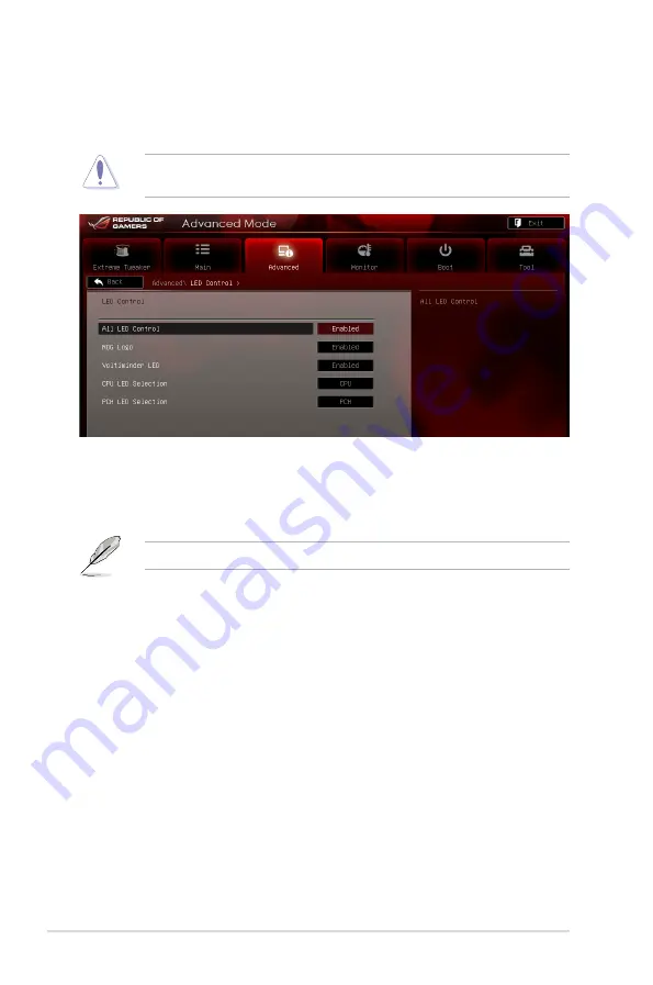
3.5.10 LED Control
The LED Control menu items allow you to change the advanced settings for the
onboard LEDs.
All LED Control [Enabled]
Allows you to enable or disable the onboard LEDs control.
Configuration options: [Enabled] [Disabled]
Take caution when changing the settings of the LED Control menu items.
Incorrect field values can cause the system to malfunction.
The following items appear only when you set
All LED Control
to [Enabled].
ROG Logo [Enabled]
Allows you to enable or disable the onboard ROG logo LED.
Configuration options: [Enabled] [Disabled]
Voltiminder LED [Enabled]
Allows you to enable or disable the onboard Voltiminder LED.
Configuration options: [Enabled] [Disabled]
CPU LED Selection [CPU]
Allows you to switch the onboard CPU LED display between CPU voltage [CPU],
VCCSA voltage [VCCSA], VCCIO voltage [VCCIO], and CPU PLL [CPU PLL].
Configuration options: [CPU] [VCCSA] [VCCIO] [CPU PLL]
PCH LED Selection [PCH]
Allows you to switch the onboard PCH LED display between PCH voltage [PCH],
and PCH PLL [PCH PLL]. Configuration options: [PCH] [PCH PLL]
Summary of Contents for Maximus iv extreme rev 3
Page 1: ...Motherboard Maximus IV Extreme Z ...
Page 73: ...A B 1 2 3 2 3 2 CPU installation ASUS Maximus IV Extreme Z 2 41 ...
Page 74: ...C B A 5 6 4 2 42 Chapter 2 Hardware information ...
Page 77: ...1 2 3 To remove a DIMM 2 3 4 DIMM installation B A ASUS Maximus IV Extreme Z 2 45 ...
Page 80: ...2 3 6 ATX Power connection 1 2 OR OR 2 48 Chapter 2 Hardware information ...
Page 81: ...2 3 7 SATA device connection OR 2 OR 1 ASUS Maximus IV Extreme Z 2 49 ...
Page 90: ...2 58 Chapter 2 Hardware information ...
Page 180: ...4 36 Chapter 4 Software support ...