background image

English

5

All-in-one PC ET2012 Series

Notices

Federal Communications Commission Statement

This device complies with Part 15 of the FCC Rules. Operation is subject to the following two 
conditions:

•  This device may not cause harmful interference, and
•  This device must accept any interference received including interference that may cause 

undesired operation.

This equipment has been tested and found to comply with the limits for a Class B digital 
device, pursuant to Part 15 of the FCC Rules. These limits are designed to provide reasonable 
protection against harmful interference in a residential installation. This equipment generates, 
uses and can radiate radio frequency energy and, if not installed and used in accordance 
with manufacturer’s instructions, may cause harmful interference to radio communications. 
However, there is no guarantee that interference will not occur in a particular installation. If 
this equipment does cause harmful interference to radio or television reception, which can be 
determined by turning the equipment off and on, the user is encouraged to try to correct the 
interference by one or more of the following measures:

•  Reorient or relocate the receiving antenna.
•  Increase the separation between the equipment and receiver.
•  Connect the equipment to an outlet on a circuit different from that to which the receiver is 

connected.

•  Consult the dealer or an experienced radio/TV technician for help.

CAUTION:

 Any changes or modifications not expressly approved by the grantee of this device 

could void the user’s authority to operate the equipment.

RF exposure warning

This equipment must be installed and operated in accordance with provided instructions and 
the antenna(s) used for this transmitter must be installed to provide a separation distance 
of at least 20 cm from all persons and must not be co-located or operating in conjunction 
with any other antenna or transmitter. End-users and installers must be provide with antenna 
installation instructions and transmitter operating conditions for satisfying RF exposure 
compliance.

Summary of Contents for ET2012AGKB

Page 1: ...English User Manual ET2012 Series MENU MODE ...

Page 2: ...en permission of ASUSTeK COMPUTER INC ASUS Products and corporate names mentioned in this manual may or may not be registered trademarks or copyrights of their respective companies and are used for identification purposes only All trademarks are the property of their respective owners Every effort has been made to ensure that the contents of this manual are correct and up to date However the manuf...

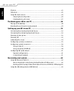
Page 3: ...CH 9 Global Environmental Regulation Compliance and Declaration 10 ASUS Recycling Takeback Services 10 UL Safety Precaution 10 ENERGY STAR complied product 11 Notes for this manual 11 Safety information 12 Setting up your system 12 Care during use 12 Sound Pressure Warning 13 TV Tuner on selected models 13 Adapter 13 DC Fan Warning 13 Welcome 14 Package contents 14 Getting to know your All in one ...

Page 4: ...d and mouse 32 Powering on the system 33 Powering off 33 Calibrating the screen 34 Configuring a wireless connection 35 Configuring a wired connection 36 Using a static IP 36 Using a dynamic IP PPPoE 38 Configuring the audio output 41 Speaker configurations 41 Connecting to speakers 41 Recovering your system 42 Using the Recovery Partition 42 Recovering the OS to the Factory Default Partition F9 R...

Page 5: ...ause harmful interference to radio or television reception which can be determined by turning the equipment off and on the user is encouraged to try to correct the interference by one or more of the following measures Reorient or relocate the receiving antenna Increase the separation between the equipment and receiver Connect the equipment to an outlet on a circuit different from that to which the...

Page 6: ...End users must follow the specific operating instructions for satisfying RF exposure compliance Operation is subject to the following two conditions This device may not cause interference and This device must accept any interference including interference that may cause undesired operation of the device Declaration of Conformity R TTE directive 1999 5 EC The following items were completed and are ...

Page 7: ...e the user may be required to take adequate measures CE marking for devices without wireless LAN Bluetooth The shipped version of this device complies with the requirements of the EEC directives 2004 108 EC Electromagnetic compatibility and 2006 95 EC Low voltage directive CE marking for devices with wireless LAN Bluetooth This equipment complies with the requirements of Directive 1999 5 EC of the...

Page 8: ... band Maximum authorized power indoors is 100mW Maximum authorized power outdoors is 10mW Departments in which the use of the 2400 2483 5 MHz band is permitted with an EIRP of less than 100mW indoors and less than 10mW outdoors 01 Ain 02 Aisne 03 Allier 05 Hautes Alpes 08 Ardennes 09 Ariège 11 Aude 12 Aveyron 16 Charente 24 Dordogne 25 Doubs 26 Drôme 32 Gers 36 Indre 37 Indre et Loire 41 Loir et C...

Page 9: ...cal electronic equipment and mercury containing button cell battery should not be placed in municipal waste Check local regulations for disposal of electronic products REACH Complying with the REACH Registration Evaluation Authorization and Restriction of Chemicals regulatory framework we publish the chemical substances in our products at ASUS REACH website at http csr asus com english REACH htm D...

Page 10: ...US Recycling Takeback Services ASUS recycling and takeback programs come from our commitment to the highest standards for protecting our environment We believe in providing solutions for you to be able to responsibly recycle our products batteries other components as well as the packaging materials Please go to http csr asus com english Takeback htm for detailed recycling information in different ...

Page 11: ...ion ENERGY STAR complied product ENERGY STAR is a joint program of the U S Environmental Protection Agency and the U S Department of Energy helping us all save money and protect the environment through energy efficient products and practices All ASUS products with the ENERGY STAR logo comply with the ENERGY STAR standard and the power management feature is enabled by default The monitor and comput...

Page 12: ... Do not walk on the power cord or allow anything to rest on it Do not spill water or any other liquids on your system When the system is turned off a small amount of electrical current still flows Always unplug all power modem and network cables from the power outlets before cleaning the system The touch screen requires periodic cleaning to achieve the best touch sensitivity Keep the screen clean ...

Page 13: ...d in particular specify that the Coaxial cable shield be connected to the grounding system of the building as close to the point of cable entry as practical Adapter 1 Adapter information varies with the purchased model a Input voltage 100 240Vac Input frequency 50 60Hz Rating output current 120W 19V 6 32A Rating output voltage 19Vdc b Input voltage 100 240Vac Input frequency 50 60Hz Rating output ...

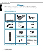
Page 14: ...ing contact your retailer Package contents All in one PC ET2012 Series Keyboard optional Mouse optional AC adapter Power cord Warranty card Wall mount screws optional KBM USB receiver dongle optional Note 1 The keyboard mouse and power supply illustrations are for reference only Actual product specifications may vary with territories 2 Keyboard and mouse can be wired or wireless Remote Control opt...

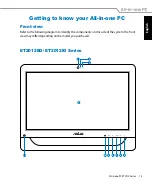
Page 15: ...g to know your All in one PC Front view Refer to the following diagram to identify the components on this side of the system The front view may differ depending on the model you purchased ET2012EG ET2012IG Series MENU MODE 3 4 6 5 7 2 8 10 9 11 1 ...

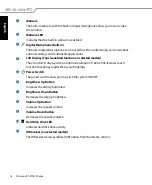
Page 16: ...al life to your fingertips 5 Power Switch The power switch allows you to switch the system ON OFF 6 Volume Up Button Press to increase the volume Press to scroll up when navigating the menu 7 MENU Button Press to display the menu Press this button to enter select the icon function highlighted while the OSD is activated 8 Volume Down Button Press to decrease the volume Press to scroll down when nav...

Page 17: ...English 17 All in one PC ET2012 Series ET2012EU ET2012IU ET2012A Series 3 4 6 5 7 2 8 10 9 11 1 ...

Page 18: ...on on selected models The 20 inch LCD display with an optimal resolution of 1600 x 900 features touch function that brings digital life to your fingertips 5 Power Switch The power switch allows you to switch the system ON OFF 6 Brightness Up Button Increases the display brightness 7 Brightness Down Button Decreases the display brightness 8 Volume Up Button Increases the speaker volume 9 Volume Dow...

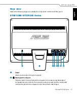
Page 19: ...Allows you to position the system upright 2 Kensington Lock port The Kensington lock port allows the computer to be secured using Kensington compatible security products These security products usually include a metal cable and lock that prevent the computer to be removed from a fixed object ANT CABLE 1 2 3 4 5 6 7 8 ET2012EG ET2012IG Series ...

Page 20: ...hard disk drives 5 HDMI input port HDMI High Definition Multimedia Interface is an uncompressed all digital audio video interface between any audio video source such as a set top box DVD player 6 Display Monitor Output The 15 pin D sub monitor port supports a standard VGA compatible device such as a monitor or projector to allow viewing on a larger external display 7 LAN port The eight pin RJ 45 L...

Page 21: ...system upright 2 Kensington Lock port The Kensington lock port allows the computer to be secured using Kensington compatible security products These security products usually include a metal cable and lock that prevent the computer to be removed from a fixed object ET2012EU ET2012IU Series ...

Page 22: ...r and keep it away from your body 4 USB port The Universal Serial Bus USB port is compatible with USB devices such as keyboards mouse devices cameras and hard disk drives 5 Display Monitor Output The 15 pin D sub monitor port supports a standard VGA compatible device such as a monitor or projector to allow viewing on a larger external display 6 LAN port The eight pin RJ 45 LAN port supports a stan...

Page 23: ...ion the system upright 2 Kensington Lock port The Kensington lock port allows the computer to be secured using Kensington compatible security products These security products usually include a metal cable and lock that prevent the computer to be removed from a fixed object ET2012A ...

Page 24: ...ort is compatible with USB devices such as keyboards mouse devices cameras and hard disk drives 5 Display Monitor Output on selected model The 15 pin D sub monitor port supports a standard VGA compatible device such as a monitor or projector to allow viewing on a larger external display 6 LAN port The eight pin RJ 45 LAN port supports a standard Ethernet cable for connection to a local network 7 A...

Page 25: ...ard disk drives 3 HDMI output port HDMI High Definition Multimedia Interface is an uncompressed all digital audio video interface between any audio video source such as a set top box DVD player 4 Microphone jack The microphone jack is designed to connect a microphone used for video conferencing voice narrations or simple audio recordings 5 Headphone Audio Out jack The stereo headphone jack 3 5mm i...

Page 26: ...our touch functions like a mouse device Touch left click on the mouse Touch and hold right click on the mouse The touch enabled screen is available on selected models Showing the touch pointer The touch pointer virtual mouse helps you use the touch enabled screen more conveniently To show the touch pointer 1 From the Windows desktop click Start Control Panel View Devices and Printer ...

Page 27: ...l amount of a household glass cleaner onto the supplied cleaning cloth and gently wipe the screen surface and the screen frame Do not spray the cleaner directly on the screen Do not use an abrasive cleaner or a coarse cloth when cleaning the screen 3 Click the Touch tab on the top and click the box before Show the touch pointer when I m interacting with items on the screen Click OK to finish the c...

Page 28: ...ll in one PC Placing on the desktop Place your All in one PC on a flat surface such as a table or desk and pull the stand open until it snaps in place Then tilt the display panel to an angle of between 12 and 30 degrees from an upright position 12O 0O 30O 0O ...

Page 29: ...0 100mm x 100mm Install the wall mount screws according to the following instructions 1 Place your All in one PC face down on a flat surface such as a table or desk and then remove the two screws beside the stand Keep the screws for future use in case you want to reinstall the stand 2 To release the stand press the stand downward shove it forward and lift Take out the stand and put it aside 1 2 3 ...

Page 30: ...English 30 All in one PC ET2012 Series 4 Secure the four wall mount screws to the rear panel holes 3 Remove the four rubber caps from the rear panel holes ...

Page 31: ... Follow the instructions described in the installation manual that came with your wall mount kit The wall mount screws are optional accessories The wall mount kit should comply with VESA 100 standards which can be purchased separately To ensure safety please read the wall mount kit installation manual carefully before mounting your All in one PC to the wall ...

Page 32: ...side 2 if the keyboard and mouse cable is not long enough The illustrations above are for reference only Actual appearances and specifications wired or wireless of the keyboard and mouse may vary with territories Connecting the wireless keyboard and mouse 1 Install batteries to the wireless keyboard and mouse 2 Insert the wireless keyboard mouse receiver to the USB port on the All in one PC 3 You ...

Page 33: ...suspend mode press the Power switch on the front panel To bring the system back to the OS press the Power switch again click the mouse touch the display or press any key on the keyboard To shut down the system completely follow the normal Windows shutdown process or press and hold the Power switch for five seconds WARNING DO NOT connect the AC power cord to an AC outlet prior to connecting the DC ...

Page 34: ... and click Calibrate the screen for pen or touch input 3 To provide calibration samples tap the crosshair each time that it appears on the screen Right click anywhere on the screen to return to the last calibration point Press the Esc key on the keyboard to close the tool Do not change your screen orientation until you have completed the calibration process The touch enabled screen is available on...

Page 35: ...security enabled network 2 Select the wireless access point you want to connect to from the list and click Connect to build the connection If you cannot find the desired access point click the Refresh icon on the upper right corner to refresh and search in the list again 3 After a connection has been established the connection is shown on the list 4 You can see the wireless network icon in the Not...

Page 36: ... click Local Area Connection and select Properties 2 Click Change adapter settings in the left pane 1 Click the network icon with a yellow warning triangle in the Windows Notification area and select Open Network and Sharing Center Ensure that you have connected the LAN cable to the All in one PC ...

Page 37: ...ing IP address 6 Enter your IP address Subnet mask and Default gateway 7 If needed enter the Preferred DNS server address 8 After entering all the related values click OK to finish the configuration 4 Click Internet Protocol Version 4 TCP IPv4 and click Properties ...

Page 38: ...steps 1 4 in the previous section 2 Select Obtain an IP address automatically and click OK Continue the following steps if using PPPoE 3 Return to the Network and Sharing Center and then click Set up a new connection or network 4 Select Connect to the Internet and click Next ...

Page 39: ...English 39 All in one PC ET2012 Series 5 Select Broadband PPPoE and click Next 6 Enter your User name and Password and Connection name Click Connect 7 Click Close to finish the configuration ...

Page 40: ...lish 40 All in one PC ET2012 Series 8 Click the network icon in the notification area and click the connection you just created 9 Enter your user name and password Click Connect to connect to the Internet ...

Page 41: ...peaker set is a left right two channel speaker system A multi channel audio speaker has a left right front and left right rear surround channel Name Speaker system 2 channel stereo Left speaker and right speaker Audio jack Headphones 2 channel Audio Out Mic In Connecting to speakers Refer to the table below for the audio jacks on the left panel and their functions For stereo speakers or headphones...

Page 42: ...ent to a USB Drive and click Next 3 Connect a USB storage device to your PC to start the Factory Default Environment backup The required size of the connected USB storage device should be larger than 20GB The actual size may vary with your PC model 4 Select a desired USB storage device if more than one USB storage device is connected to your All in one PC and click Next If there is already a parti...

Page 43: ...S to the Default Partition only Select this option if you simply want to restore the OS to the factory default partition This option deletes all data on the system partition C and keeps the partition D unchanged After you click Next the factory default partition will be displayed Click Next again Restore the Whole Hard Disk Select this option if you want to restore your All in one PC to the factor...

Page 44: ... Series Manufacturer ASUSTek COMPUTER INC Address City No 150 LI TE RD PEITOU TAIPEI 112 TAIWAN R O C Country TAIWAN Authorized Representative in Europe ASUS COMPUTER GmbH Address City HARKORT STR 21 23 40880 RATINGEN Country GERMANY ...

Reviews: