


Chapter 3: Motherboard Information
3-16
3.5
Internal connectors
1.
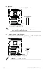
Serial port connector (10-1 pin COM1)
This connector is for the serial (COM) port. Connect the serial port module cable to one
of these connectors, then install the module to a slot opening at the back of the system
chassis.
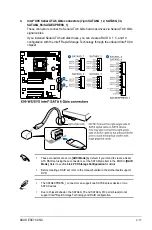
2.
Digital audio connector (4-1 pin SPDIF_OUT)
This connector is for an additional Sony/Philips Digital Interface (S/PDIF) port. Connect
the S/PDIF Out module cable to this connector, then install the module to a slot
opening at the back of the system chassis.
The S/PDIF module is purchased separately.
Summary of Contents for ESC700
Page 1: ...Workstation ESC700 G3 User Guide ...
Page 23: ...2 5 ASUS ESC700 G3 A B B C A B A Triangle mark Triangle mark ...
Page 48: ...Chapter 2 Hardware Setup 2 30 ...
Page 76: ...Chapter 3 Motherboard Information 3 28 ...
Page 148: ...5 10 Chapter 5 RAID Configuration ...
Page 157: ...A Appendix Appendix ...


