


Chapter 3
–
AMI BIOS Setup
60
3.5
”
Sub
co
m
pa
ct
Bo
ard
G
EN
E-
KB
U6
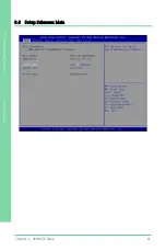
3.1 System Test and Initialization
The board uses certain routines to perform testing and initialization during the boot up
sequence. If an error, fatal or non-fatal, is encountered, the system will output a few
short beeps or an error message. The board can usually continue the boot up
sequence with non-fatal errors.
The system configuration verification routines check the current system configuration
against the values stored in the CMOS memory. If they do not match, an error message
will be output, and the BIOS setup program will need to be run to set the configuration
information in memory.
There are three situations in which the CMOS settings will need to be set or changed:
-
Starting the system for the first time
-
The system hardware has been changed
-
The CMOS memory has lost power and the configuration information is erased
The system
’
s CMOS memory uses a backup battery for data retention. The battery
must be replaced when it runs down.
Summary of Contents for AAEON GENE-KBU6
Page 1: ...Last Updated October 28 2021 GENE KBU6 3 5 Subcompact Board User s Manual 1st Ed ...
Page 15: ...3 5 Subcompact Board GENE KBU6 Chapter 1 Chapter 1 Product Specifications ...
Page 20: ...3 5 Subcompact Board GENE KBU6 Chapter 2 Chapter 2 Hardware Information ...
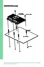
Page 69: ...Chapter 2 Hardware Information 55 3 5 Subcompact Board GENE KBU6 GENE KBU6 HSK02 Assembly ...
Page 71: ...Chapter 2 Hardware Information 57 3 5 Subcompact Board GENE KBU6 GENE KBU6 FAN01 Assembly ...
Page 73: ...3 5 Subcompact Board GENE KBU6 Chapter 3 Chapter 3 AMI BIOS Setup ...
Page 76: ...Chapter 3 AMI BIOS Setup 62 3 5 Subcompact Board GENE KBU6 3 3 Setup Submenu Main ...
Page 77: ...Chapter 3 AMI BIOS Setup 63 3 5 Subcompact Board GENE KBU6 3 4 Setup Submenu Advanced ...
Page 86: ...Chapter 3 AMI BIOS Setup 72 3 5 Subcompact Board GENE KBU6 3 4 5 SIO Configuration ...
Page 96: ...Chapter 3 AMI BIOS Setup 82 3 5 Subcompact Board GENE KBU6 3 5 Setup Submenu Chipset ...
Page 107: ...Chapter 3 AMI BIOS Setup 93 3 5 Subcompact Board GENE KBU6 3 8 Setup submenu Save Exit ...
Page 108: ...3 5 Subcompact Board GENE KBU6 Chapter 4 Chapter 4 Drivers Installation ...
Page 112: ...3 5 Subcompact Board GENE KBU6 Appendix A Appendix A Watchdog Timer Programming ...
Page 117: ...3 5 Subcompact Board GENE KBU6 Appendix B Appendix B I O Information ...
Page 118: ...Appendix B I O Information 104 3 5 Subcompact Board GENE KBU6 B 1 I O Address Map ...
Page 119: ...Appendix B I O Information 105 3 5 Subcompact Board GENE KBU6 ...
Page 120: ...Appendix B I O Information 106 3 5 Subcompact Board GENE KBU6 B 2 Memory Address Map ...
Page 121: ...Appendix B I O Information 107 3 5 Subcompact Board GENE KBU6 B 3 IRQ Mapping Chart ...
Page 122: ...Appendix B I O Information 108 3 5 Subcompact Board GENE KBU6 ...
Page 123: ...Appendix B I O Information 109 3 5 Subcompact Board GENE KBU6 ...
Page 124: ...Appendix B I O Information 110 3 5 Subcompact Board GENE KBU6 ...
Page 125: ...Appendix B I O Information 111 3 5 Subcompact Board GENE KBU6 ...
Page 126: ...Appendix B I O Information 112 3 5 Subcompact Board GENE KBU6 ...
Page 127: ...Appendix B I O Information 113 3 5 Subcompact Board GENE KBU6 ...
Page 128: ...Appendix B I O Information 114 3 5 Subcompact Board GENE KBU6 ...
Page 129: ...Appendix B I O Information 115 3 5 Subcompact Board GENE KBU6 ...
Page 130: ...Appendix B I O Information 116 3 5 Subcompact Board GENE KBU6 ...
Page 131: ...Appendix B I O Information 117 3 5 Subcompact Board GENE KBU6 ...
Page 132: ...3 5 Subcompact Board GENE KBU6 Appendix C Appendix C Electrical Specifications for I O Ports ...
Page 134: ...3 5 Subcompact Board GENE KBU6 Appendix D Appendix D Digital I O Ports ...
Page 141: ...3 5 Subcompact Board GENE KBU6 Appendix E Appendix E Mating Connectors and Cables ...


