


English
28
1. High Definition Audio supports Jack Sensing, but the panel wire on the chassis must
support HDA to function correctly. Please follow the instructions in our manual and
chassis manual to install your system.
2. If you use an AC’97 audio panel, please install it to the front panel audio header by
the steps below:
A. Connect Mic_IN (MIC) to MIC2_L.
B. Connect Audio_R (RIN) to OUT2_R and Audio_L (LIN) to OUT2_L.
C. Connect Ground (GND) to Ground (GND).
D. MIC_RET and OUT_RET are for the HD audio panel only. You don’t need to con-
nect them for the AC’97 audio panel.
E. To activate the front mic, go to the “FrontMic” Tab in the Realtek Control panel
and adjust “Recording Volume”.
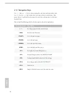
Chassis Fan Connector
(4-pin CHA_FAN1)
(see p.6, No. 20)
(3-pin CHA_FAN2)
(see p.6, No. 15)
Please connect fan cables
to the fan connectors and
match the black wire to
the ground pin.
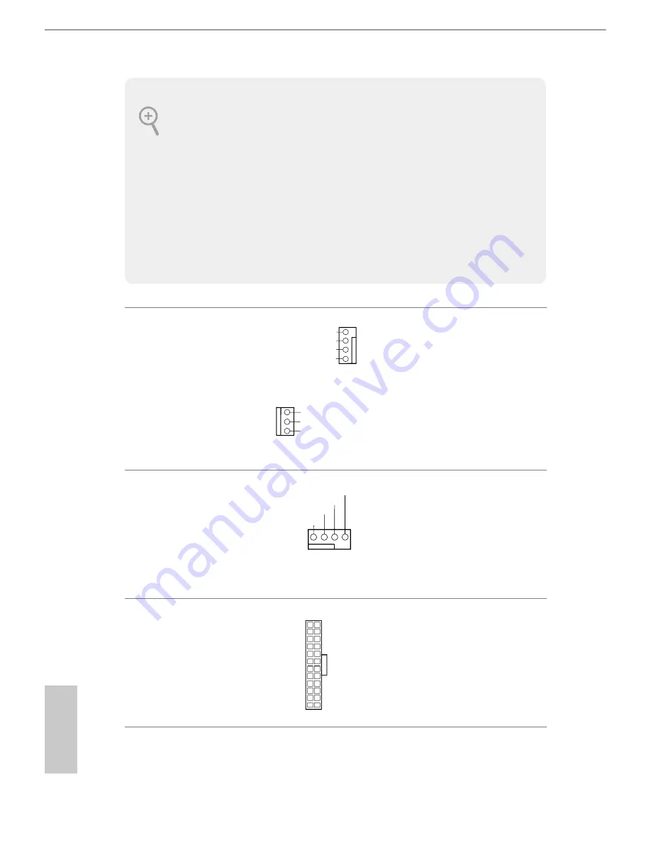
CPU Fan Connector
(4-pin CPU_FAN1)
(see p.6, No. 2)
This motherboard pro-
vides a 4-Pin CPU fan
(Quiet Fan) connector.
If you plan to connect a
3-Pin CPU fan, please
connect it to Pin 1-3.
ATX Power Connector
(24-pin ATXPWR1)
(see p.6, No. 4)
This motherboard pro-
vides a 24-pin ATX power
connector. To use a 20-pin
ATX power supply, please
plug it along Pin 1 and Pin
13.
FAN_VOLTAGE
GND
FAN_SPEED
FAN_SPEED_CONTROL
1
2
3
4
GND
CHA_FAN_SPEED
FAN_VOLTAGE
FAN_VOLTAGE
GND
CPU_FAN_SPEED
FAN_SPEED_CONTROL
1 2 3 4
12
1
24
13
Summary of Contents for A320M-DVS R3.0
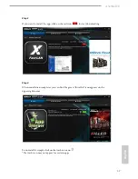
Page 1: ......
Page 17: ...English 12 3 ...
Page 19: ...English 14 3 4 C P U _ F A N 1 4 pin FAN cable ...
Page 20: ...A320M HD 15 English Installing the AM4 Box Cooler SR2 1 2 ...
Page 21: ...English 16 3 ...
Page 22: ...A320M HD 17 English 4 pin FAN cable 4 C P U _ F A N 1 ...
Page 23: ...English 18 Installing the AM4 Box Cooler SR3 1 2 ...
Page 24: ...A320M HD 19 English 3 4 ...