EFD1000 E5 Dual Electronic Flight Instrument (EFI) Install Manual
DOCUMENT # 900-00041-001
PAGE 96-226
REVISION D
© Copyright 2019 Aspen Avionics Inc.
8.5
RSM Pin Out
Pin
Number
Name
Input /
Output
Function
1
RSMA
-
RSM Connection
2
RSMB
-
RSM Connection
3
RSMC
-
RSM Connection
4
RSMD
-
RSM Connection
5
RSME
-
RSM Connection
6
RSMF
-
RSM Connection
7
RSMG
-
RSM Connection
Table 8-11: RSM Pin Out
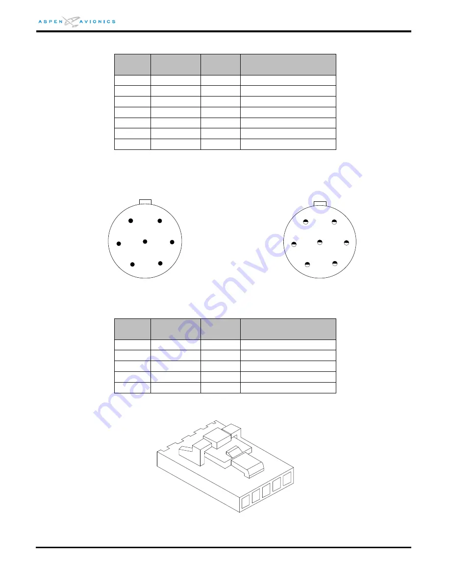
Male Pin Side
Solder Cup Side
Figure 8-2: RSM Mating Connector –Install Side
8.6
Configuration Module Pin Out
Pin
Number
Name
Input /
Output
Function
1
ConfigA
-
CM Connection
2
ConfigB
-
CM Connection
3
ConfigD
-
CM Connection
4
ConfigC
-
CM Connection
5
ConfigS
-
Shield Ground
Table 8-12: Configuration Module Pin Out
Figure 8-3: Configuration Module Connector (Install side)
7
6
5
4
3
1
2
7
1
2
3
4
6
5
2
1
3
5
4


