EFD1000 E5 Dual Electronic Flight Instrument (EFI) Install Manual
DOCUMENT # 900-00041-001
PAGE 72-226
REVISION D
© Copyright 2019 Aspen Avionics Inc.
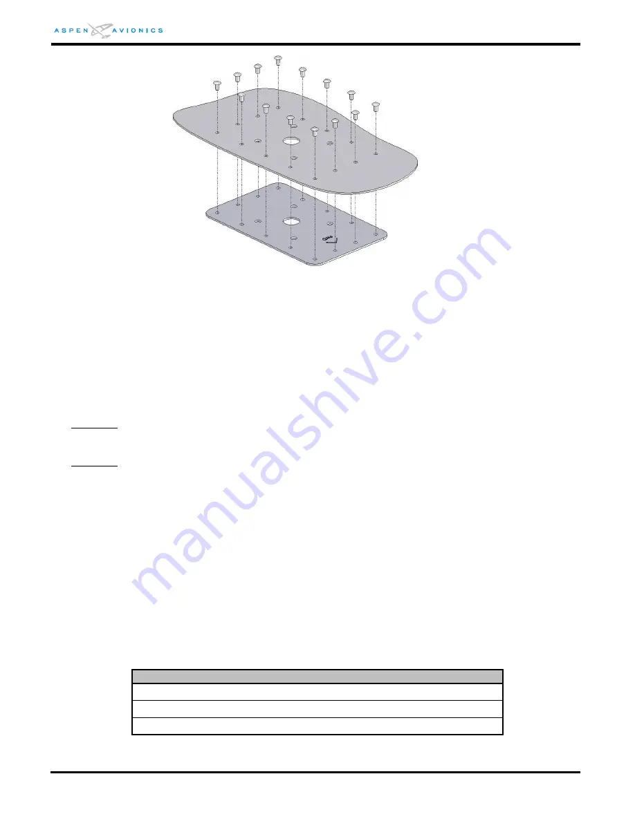
Figure 6-21: Doubler Installation
6.9.9
RSM Internal Mount
The installer must use a suitable existing shelf or fabricate a suitable mounting bracket
for internally mounting the RSM. Use AC43.13-2B Chapter 1 for additional structural
data.
6.9.10
RSM Installation
CAUTION: Do not use a magnetic tipped or electric screwdriver to mount the RSM as this may
magnetize the RSM and cause heading errors.
CAUTION: Only non-ferrous mounting hardware can be used (i.e., screws, nuts, washers, nutplates)
to mount the RSM. Use of any ferrous hardware may cause compass errors. The supplied
Brass hardware should be used.
NOTE: The RSM contains a sensitive magnetometer. Nearby ferrous components or hardware can
magnetize the RSM and/or cause erroneous indications.
1)
It is not required to remove aircraft surface paint below RSM unless an aluminum shim was
required on extreme mounting angles. The shim must be bonded to the fuselage. Bonding
of RSM is through four (4) mounting screws to doubler.
2)
Install ring terminal to RSM shield ground wire.
3)
Install RSM on aircraft and secure using four (4) screws, four (4) washers, and four (4) nuts
as identified below. Installer may substitute non-ferrous nut plates for washers and nuts
provided the nutplates are attached to the doubler only and not the aircraft skin.
Description
8-32 Brass screw 1¼” MS35214-47
Brass locking nuts MS21044B08 (formerly AN365-B832)
Brass Washer NAS1149B0832H (formerly AN960-B8)
Table 6-4: RSM Mounting Hardware


