ASIX AXM22001-2A-C User Manual Download Page 1


      AXM22001-2A-C 

IEEE 802.11b/g WiFi Module Board User’s Guide

Copyright © 2011 ASIX Electronics Corporation. All rights reserved. 


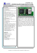
The AXM22001-2A-C is a 2.4GHz 802.11b/g WiFi module 
board which integrates AX22001 and Airoha AL2230S RF 
transceiver on board to provide a complete WiFi module 
solution with various user or host interfaces supported. The 
AXM22001-2A-C is a surface mountable module with 
castellated mounting holes which offers smaller-form-factor, 
lower-cost, pre-calibrated RF front-end and pre-certified WiFi 
module board to free the user from RF and antenna design 
tasks and regulatory compliance testing, ultimately providing 
quicker time to market. The user can design his host board with 
desired function and interface circuits and assemble it with the 
AXM22001-2A-C WiFi module board through the castellated 
mounting holes. 
 

Key Features 

y


Integrated 2.4GHz, IEEE 802.11b/g compatible 
WiFi connectivity


y


Integrated PCB antenna


y


Max outdoor range up to 300m (984 ft.), line of 
sight 

y


Supports operation in Infrastructure or Ad-Hoc 
(IBSS) network topology 

y


Supports 802.11i security: WEP-64/128, TKIP 
(WPA-PSK) and AES (WPA2-PSK) 

y


Dual 8-bit 1T 8051/80390 CPU @ 80MHz 

y


1MB shared Flash memory for MCPU and 
WCPU program code and configuration data 
storage 

y


64KB data memory for MCPU 

y


4 UART interfaces 

y


High Speed SPI interface (master or slave 
mode) 

y


I2S or PCM interface 

y


Local Bus host interface (master or slave mode)

y


MII or RMII interface 

y


I2C interface 

y


Up to 32 GPIOs (4 GPIO ports of 8 bits each) 

y


Supports real-time clock, with option to use 
independent power supply from lithium battery 

y


Supports TCP, UDP, ICMP, IGMP, IPv4, 
DHCP, BOOTP, ARP, DNS, SMTP, SNTP, 
UPnP, PPPoE and HTTP in software 

y


Supports network boot over Ethernet or WiFi 
using BOOTP and TFTP 

y


Single operating voltage: 3.3V typical 

y


Board size: 51.0mm x 28.0mm x 4.5mm 
surface mountable module 


Applications  

y


Serial to WiFi Device Server 

y


WiFi Speaker 

y


WiFi Remote Control/Monitor 

y


Ethernet to WiFi Bridge 

y


Zigbee to WiFi Bridge 

y


WiFi Network Camera 

y


WiFi RFID 

y


SPI to WiFi Bridge 

y


TCP/IP and WLAN Offload Co-processor 

y


WiFi Internet Radio 


Model Name: AXM22001-2A-C 

Document No: AXM22001-2A-C/V1.01/11/07/11

Summary of Contents for AXM22001-2A-C

Page 1: ...pports operation in Infrastructure or Ad Hoc IBSS network topology y Supports 802 11i security WEP 64 128 TKIP WPA PSK and AES WPA2 PSK y Dual 8 bit 1T 8051 80390 CPU 80MHz y 1MB shared Flash memory f...

Page 2: ...inout 3V3_PAS 3V3_PAS GND GND GND GND GND P20 P21 P22 P23 P24 P25 P26 P27 XTL32KO XTL32KI VCC18A_RTCI 1V8 LB_CLK WLED SYSCK_SEL XDATA1 XDATA2 XDATA4 XDATA5 XDATA6 RST_N GND GND GND GND GND 3V3_RF 3V3_...

Page 3: ...rystal I O and RTC logic 19 J2 14 1V8 PO 1 8V power output 20 J2 15 LB_CLK B Local bus clock input or output 21 J2 16 WLED O WiFi link status LED 22 J2 17 SYSCK_SEL I Operating system clock frequency...

Page 4: ...4 15 MISO B MISO LDA15 WDB_DO signals 65 J4 16 P37 B P37 LDA7 Y7 DTR2 CEX4 signals 66 J4 17 P36 B P36 LDA6 Y6 RTS2 CEX3 signals 67 J4 18 P35 B P35 LDA5 Y5 DCD2 CEX2 signals 68 J4 19 P34 B P34 LDA4 Y4...

Page 5: ...Guide Copyright 2011 ASIX Electronics Corporation All rights reserved Board Dimensions The AXM22001 2A C is a surface mountable module with castellated mounting holes on three sides Below shows the mo...

Page 6: ...ost PCB footprints for the module The AXM22001 2A C module has an integrated PCB antenna which requires the host PCB to maintain certain copper keep out area as shown below for best antenna performanc...

Page 7: ...2011 ASIX Electronics Corporation All rights reserved Module Reflow Profile Zone AD1 AD2 AD3 AD4 AD5 AD6 AD7 AD8 Upper Limit 170 175 185 190 195 225 275 260 Lower Limit 170 0 0 0 0 225 275 260 Time S...

Page 8: ...er trace and plane It is recommended that the module be mounted on the edge of the host PCB To have best performance place the module on the host PCB according to the details shown in Figure 3 The ant...

Page 9: ...are designed to provide reasonable protection against harmful interference in a residential installation This equipment generates uses and can radiate radio frequency energy and if not installed and u...

Page 10: ...antenna of for this device and the persons must be 20 cm or more during operation This device must not be co located or operating in conjunction with any other antenna or transmitter If the AXM22001...

Page 11: ...d user is responsible for ensuring compliance with harmonized frequencies and labeling requirements for each country in which the end device is marketed and sold Helpful Web Sites Radio and Telecommun...

Reviews: