background image

Ascotel® IntelliGate® 2025/2045/2065 as of I7.9

Operation and Maintenance

181

sy

d-

020

4/1.

– I7.

9

 – 1

2

.2009

6

Operation and Maintenance

This chapter describes maintaining the system and configuration data as well as up-
dating the system software. Replacing cards, modules and terminals are also described. 
The user interface of the basic system as well as operations supervision using the event 
message concept, the operating state display, and the error display are also topics cov-
ered in this chapter.

6. 1

Data Maintenance

6. 1. 1

What data is stored where

The PBX’s data storage system consists of three elements:

In the Flash components are stored the system software, the boot software and 
the configuration data. The contents of the memory are retained even when 
there is no power supply.

In the RAM components (main memory) are stored volatile data that cannot be 
saved. It is available only when the system is in operation.

The EIM card (Equipment Identification Module) contains the system-specific 
data (system ID, system type, sales channel, licence code, generation, DECT iden-
tification numbers), IP address of the Ethernet interface on the mainboard).

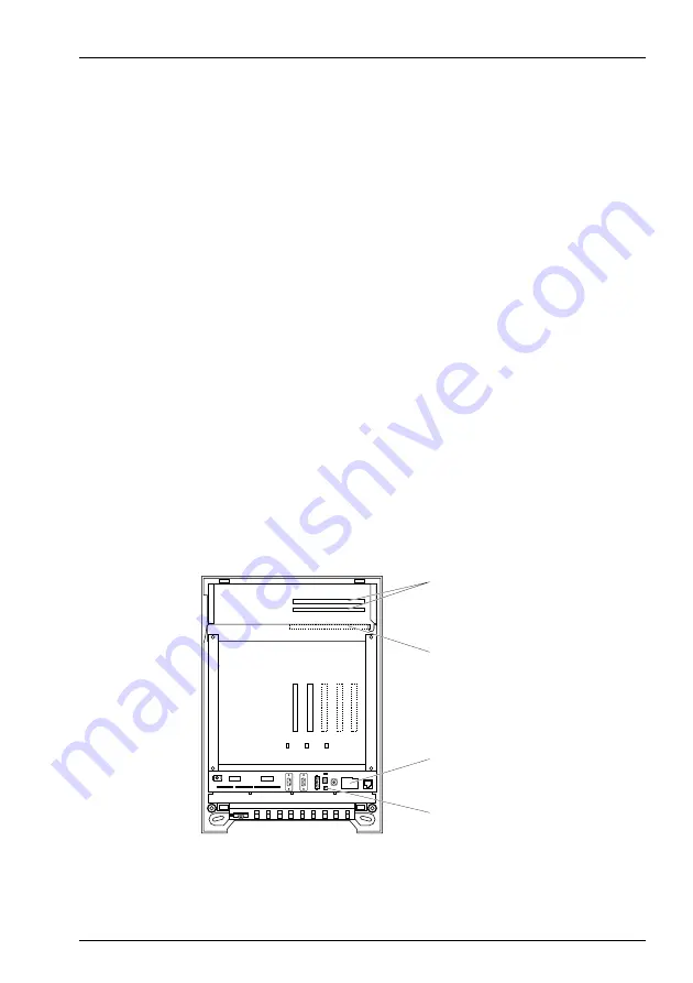
Fig. 91

Memories on the mainboard 2025/2045

Massstab 1:10

System slots for 
Flash cards

System slot,
RAM card

EIM card

1

80

84

1

Prog. button

haz1223aaenc0

Summary of Contents for 2025

Page 1: ...2025 2045 2065 Ascotel IntelliGate Communications Systems Ascotel IntelliGate 2025 2045 2065 as of I7 9 System Manual ...

Page 2: ...upply module 29 3 4 2 Auxiliary Terminal Power Supply ATPS 29 3 5 Expansion cards 30 3 5 1 Trunk cards 30 3 5 2 Terminal cards 31 3 5 3 Special cards 31 3 6 Ethernet switch upgrade set 38 3 7 System Limits 39 3 7 1 General System Limits 39 3 7 2 Terminals 41 3 7 3 Terminal and network interfaces 43 3 7 4 Licence related system limits 44 3 7 5 Power supply related limits 52 3 7 5 1 Supply power ava...

Page 3: ...h UPS 12V module 76 4 3 3 2 External UPS 79 4 4 Equipping the PBX 80 4 4 1 Cards 80 4 4 1 1 System cards 80 4 4 1 2 Expansion cards 80 4 5 Component Mounting Rules and Examples 83 4 5 1 Component mounting rules 83 4 5 2 Examples of component placement 83 4 6 Connecting the System 86 4 6 1 Direct connection 87 4 6 2 Indirect connection 88 4 6 2 1 Connection via main distribution board 89 4 6 2 2 Co...

Page 4: ... authorization profiles 163 5 3 1 3 Administration rights 164 5 3 1 4 Interface access 165 5 3 1 5 User accounts during version transfers 166 5 3 2 Passwords 166 5 3 2 1 Initialization password 167 5 3 2 2 Password syntax 167 5 3 2 3 Change password 168 5 3 2 4 Incorrect password 168 5 3 2 5 Lost password 168 5 3 3 Access using the System Assistant on the Office 45 168 5 3 4 Password free access 1...

Page 5: ...1 2 1 Maintaining configuration data with AIMS 184 6 1 2 2 Deleting terminal configuration data 185 6 2 Update Software 185 6 2 1 System software 185 6 2 1 1 AIMS Upload Manager 185 6 2 1 2 Standard upload 186 6 2 1 3 Emergency Upload of the system software 190 6 2 2 Updating the PBX boot software 192 6 2 3 Software of corded system terminals 192 6 2 4 Software for DECT systems 193 6 3 Hardware up...

Page 6: ...m Downgrade from I7 x x 5 to I6 6 219 6 4 12 System Downgrade from I7 5 to I7 x x 5 219 6 4 13 System Downgrade from I7 x x 5 to I7 5 220 6 5 Operations supervision 222 6 5 1 Event message concept 222 6 5 1 1 Event types 223 6 5 1 2 Event tables 227 6 5 1 3 Signal destinations 228 6 5 1 4 SNMP destination 238 6 5 2 System Event Manager SEM 239 6 5 3 Operating state and error displays 240 6 5 3 1 S...

Page 7: ...g Plate and Designation Stickers 252 7 3 Equipment Overview 253 7 4 Technical Data 254 7 4 1 Basic Systems 254 7 4 2 Expansion cards 255 7 4 3 Power Supplies 257 7 5 Functions and Products No Longer Supported 258 7 6 Licensing information of third party software products 259 7 7 Documents and Help Systems with Further Information 260 ...

Page 8: ...or other purposes or replaced by outside parts unless for the connection of other approved networks applications and terminals to the interfaces provided specially for that purpose Data protection Unencrypted phone calls made in the IP network can be recorded and played back by anyone with the right resources You should therefore prioritise the use of sepa rate leased lines for WAN links via which...

Page 9: ...led with the utmost care The functions of the product and of all part products have been checked and released as a result of extensive approval tests Nonetheless errors cannot be entirely ex cluded The manufacturers shall not be liable for any direct or indirect damage that may be caused by incorrect handling improper use or any other faulty behaviour on the part of a product Potential areas of pa...

Page 10: ...rks table of contents cross references and index All these navigation aids are linked i e a mouse click takes you directly to the corresponding places in the Manual We have also ensured that the page numbering in the PDF navigation cor responds to the page numbering of the Manual making it much easier to jump to a particular page Referenced menu entries and parameters appearing on terminal display...

Page 11: ... to other chapters within the document or to other documents Ascotel IntelliGate Net Particularities that have to be observed in an AIN Safety Considerations Special hazard alert messages with pictograms are used to signal areas of particular risk to people or equipment Hazard Failure to observe information identified in this way can put people and hardware at risk through electrical shock or shor...

Page 12: ...ipment Immediately disconnect the system from the mains as well from the UPS Electrostatic Discharge Warning The system s reliability can be adversely affected by electrostatic dis charges caused by touching electronic components and elements and subsequent damage can result Always observe the ESD guidelines Mounting Instructions Observe the following stipulations when installing the system Do not...

Page 13: ...gears music sources etc to the sys tem 1 4 During Operation The system is supplied with electrical voltage when in operation Disconnect the system from the power supply when work requires opening the inner housing cover Maintenance Work Any servicing expansion or repair work is to be carried out only by technical per sonnel with the appropriate qualifications Replacing Components Cards and modules...

Page 14: ...guration always keep the configuration planning data contained on the relevant data carriers under supervision Ensure that only authorized persons have access to the data Regulating Access to the System Configuration To ensure that only authorized persons have access to the system data consistently implement the following protective measures Change the passwords at regular intervals and keep them ...

Page 15: ...stem is par ticularly well suited for companies that operate in several locations Coverage can even be extended to the smallest branch offices at low cost Voice communication technology is currently undergoing a major leap forward New technologies such as Voice over IP VoIP are also used in small and medium sized companies A modern communications system must offer the customer the option of implem...

Page 16: ...stems One shared system for Ascotel IntelliGate 2025 and 2045 and a separate system for Ascotel IntelliGate 2065 Fig 1 Ascotel IntelliGate 2025 2045 The basic systems can be expanded with expansion cards It also includes digital and analogue trunk and terminal cards as well as special cards e g for the IP Gate way the Voice Mail System etc The number of available slots depends on the basic system ...

Page 17: ...lephony uses Special models soft phones and hardphones are also available for telephone switching The Pocket Adapter serves to connect a PC to a terminal interface Tab 1 Area of application for system terminals Area of application Office 10 Office 25 Office 35 Office 45 45pro Aastra 5360 Aastra 5370 Aastra 5380 Aastra 5360ip Aastra 5370ip Aastra 5380ip Office 135 135pro Aastra 610d Aastra 620d Aas...

Page 18: ...telliGate 2065R Rack version Positioning Applications range from small and medium sized companies and branches Asco tel IntelliGate 2025 2045 to large sized companies Ascotel IntelliGate 2065 The diagram below shows the positioning in relation to the number of users com pared with other Ascotel products The information relates to non networked stand alone systems Fig 3 Product overview in relation...

Page 19: ...cture with the integration of external workstations with IP system terminals of cordless handsets via DECT WLAN and of corded analogue or digital terminals and CTI workstations Digital or analogue network interfaces are used for the connection to the digital public network ISDN SIP or the analogue public network POTS Fig 4 Satellites in an Ascotel IntelliGate Net AIN Office 1600IP Office 1560IP Of...

Page 20: ... inter faces Ethernet ISDN V 24 Fig 5 OIP as middleware between Ascotel IntelliGate external data sources and applications OIP supports the connection of external directories and it is also possible to set up alarming and messaging systems Several Ascotel IntelliGate systems can be connected to an OIP server It is then possible for instance to obtain network wide call logging for all the systems t...

Page 21: ... Ethernet Router SIP Service Provider Ethernet Gateway Router First Party CTI via LAN with Office terminal Digital Telephony Analogue Telephony CTI and TAPI Operator console s Office 45 Fax server Third Party CTI with telephony server CTI Call Center workstations ISDN comfort sets Digital feature phones and key telephones Integrated DECT system Fax 1 3 IP Terminals Two wire door intercom system wi...

Page 22: ...ject Man ager 3 1 Overview The expansion possibilities of the basic systems 2025 2045 and 2065 at a glance Fig 7 System overview 3 2 System Family The system family consists of three systems Ascotel IntelliGate 2025 Ascotel IntelliGate 2045 Ascotel IntelliGate 2065 DSPX 02 haz1210aaend0 Basic system 2025 2045 Basic system 2065 Special cards DRS 08 DRS 04 OI 2DOOR AIP 6400 DSP 04 DSP 02 UPS 12V Pow...

Page 23: ...Basic systems and number of expansion slots per system Tab 3 Resources of the basic systems Basic system Expansion slots Ascotel IntelliGate 2025 2025 2045 5 Ascotel IntelliGate 2045 2025 2045 5 Ascotel IntelliGate 2065 2065 141 1 An additional slot No 8 is reserved for the processor card Circuits for the functions Three party conference Six party conference Intru sion and Silent intrusion 1 1 The...

Page 24: ... the basis for the systems Ascotel IntelliGate 2025 and Ascotel IntelliGate 2045 It consists of the following components 2025 2045 housing Main board 2025 2045 incl power supply Memory cards RAM Flash EIM Fig 8 2025 2045 basic system Massstab 1 10 Massstab 1 10 Power supply connections for integrated interfaces Earthing connection Expansion slots Housing cover haz1211aaenc0 ...

Page 25: ...Tab 31 System a b S T switchable AD2 V 24 Ethernet interfaces Audio interfaces Relay for General Bell Auxiliary power sup ply ATPS 2025 2045 3 3 4 2 1 1 1 10 Base T half duplex 1 1 1 Massstab 1 10 System slots for RAM and Flash cards Expansion slots EIM card S T switchover jumper MBS 1 Power supply V 24 interfaces a b interfaces and floating relay contact for general bell Ethernet interface Plug f...

Page 26: ...sic system provides the basis for the Ascotel IntelliGate 2065 system It consists of the following components 2065 housing Main board 2065 incl power supply Processor card MPC 8260 Memory cards Fig 10 2065 basic system Massstab 1 10 Massstab 1 10 Power supply Housing cover haz1212aaenc0 Slot for processor card Expansion slots Earthing connection ...

Page 27: ...s to cables and clamps see Tab 31 System V 24 Ethernet interface Audio Interfaces Relay for Gen eral Bell Auxiliary power supply ATPS 2065 2 1 1 On the Ascotel IntelliGate 2065 the processor card MPC 8260 has 1 Ethernet interface 10 100Base T half full duplex Full duplex only if the connected switch port is configured to automatic 1 1 1 Massstab 1 10 Potential free relay contacts for a general bel...

Page 28: ...sor card MPC 8260 Processor card MPC 8260 contains the system processor the RAM card and the Ethernet interface for the Ascotel 2065 basic system Memory cards Tab 6 Memory cards per system Another slot is provided so the system can be subsequently expanded with a sec ond Flash card 2025 system 2045 system 2065 system Flash card 8 MByte parallel 64 MByte serial 8 MByte parallel 64 MByte serial 8 MB...

Page 29: ...an expansion slot 3 4 2 Auxiliary Terminal Power Supply ATPS The external Auxiliary Terminal Power Supply ATPS is used to increase the supply power available for the terminals It is required only for system expansions with a many terminals with high power requirements e g a large number of DECT radio units without their own power supplies see also Power supply related limits page 52 The ATPS power...

Page 30: ...ate 2025 However the number of interfaces enabled is determined in each case by the sys tem limits There are 3 types of expansion cards available for expanding the basic systems Trunk cards Terminal cards Special cards 3 5 1 Trunk cards Trunk cards expand the number of network interfaces available to a system Tab 7 Number of trunk cards of one particular type per system Card type Network interface...

Page 31: ...Ascotel IP gate way AIP 6400 The applications are VoIP Voice over Internet Protocol and QSIG networking in the IP network The card makes it possible to network multiple PBXs in different locations via an existing voice compatible IP network With the AIP 6500 software the card functionally becomes an Ascotel IP gate way AIP 6500 Several Ascotel IntelliGate systems can be connected in this way via I...

Page 32: ...ypes which differ in the number of Voice Mail channels and recording time Only one of these cards can be installed per sys tem Tab 10 Resources of the Voice Mail cards Ascotel IntelliGate Net In an AIN a Voice Mail card can only be operated in the Master It is not possible to operate Voice Mail cards in satellites not even in offline mode A separate documentation is available with details of this ...

Page 33: ...SM terminals or fax transmissions This means that for each DSP chip a specific number of voice channels is available for the corresponding functions Some of these functions are subject to a licence see also Licence re lated system limits page 44 DECT Operation of a DECT system with cordless terminals In the case of connections between DECT and non DECT environments the voice data has to be convert...

Page 34: ...annels are available with the licence Each additional Voice Mail channel requires an additional Enter prise Voice Mail Channels licence With additional licences the voice memory ca pacity can be increased to a total of 400 minutes Additional Voice Mail Recording Time licence the Auto Attendant function can then also be used Auto Attend ant licence The operating mode for the Voice Mail System is de...

Page 35: ...th different DSP chips and therefore provide a different number of voice channels for each DSP chip The tables below show all the possible combinations with the maximum number of voice channels for the DSP chips on the different DSP cards Tab 13 Max number of voice channels for DSP chips on DSP 01 DSP 02 Tab 14 Max number of voice channels for DSP chips on DSP 04 DSP card Number of DSP chips DSP 0...

Page 36: ...e two basic Voice Mail chan nels that can be used without a licence are redundant The system has to be restarted for the configuration changes of the DSP to take effect After a first start all the DSP chips are configured on DECT DECT VoIP1 1 Licence s required see also Licence related system limits page 44 FoIP1 Voice mail1 GSM1 Remarks 10 8 10 5 4 10 4 8 Voice Mail only G 729 4 6 10 Voice Mail o...

Page 37: ...hips and provides voice channels for DECT VoIP Basic Enterprise Voice Mail and for full duplex hands free operation DSP 02 Contains 4 DSP chips and provides voice channels for DECT VoIP Basic Enterprise Voice Mail and for full duplex hands free operation DSP 04 Contains 5 DSP chips and provides voice channels for DECT VoIP Basic Enterprise Voice Mail and for full duplex hands free operation DSPX 0...

Page 38: ...lex2 Auto negotiation Auto MDI MDIX automatic detection allows the use of straight or crossover LAN cables No programming or configuration via AIMS required Depending on requirements the upgrade set may comprise a basic set and one or two expansion sets each with one options card OSWI8 and the relevant installa tion material A total of three options cards with 8 LAN ports each can be fitted to a 2...

Page 39: ...T internal external 16 36 80 cumulated DECT DECT internal 15 30 120 cumulated VoIP VoIP via SIP access9 external 303 603 1205 cumulated VoIP not VoIP internal external 22 38 886 cumulated VoIP channels with AIP 6400 1 x 12 2 x 12 4 x 12 cumulated VoIP channels with AIP 6500 1 x 16 2 x 16 4 x 16 cumulated VoIP channels without AIP cards9 6 6 246 cumulated Total of VoIP channels9 22 38 766 cumulated...

Page 40: ... 16 as for 2065 User per announcement message group 16 16 16 as for 2065 Data service tables 8 8 32 as for 2065 X 25 D channels 3 5 16 as for 2065 User accounts for User Access Control 25 25 25 as for 2065 Authorization profiles for user accounts 25 25 25 as for 2065 Log entries per user account 20 20 20 as for 2065 First party CTI users via LAN9 30 32 32 as for 2065 Third party CTI interfaces 1 1...

Page 41: ... number of terminals 4 Limited by the software hardware limits 5 Limited by the licence limits 6 Only with DSPX 02 DSP cards and MPC 3 F processor card otherwise only 12 channels 7 With expansion card VM 02P VM 04P 8 Only with DSPX 02 DSP card 9 Licences required 10 With AVS software V6 6 or later 11 In an AIN a Voice Mail card can only be operated in the Master It is not possible to operate Voice...

Page 42: ...SB 8ANT radio units 4 18 128 as for 2065 2 DECT Handsets Office 135 Office 160pro Aastra 610d Aastra 620d Aastra 630d DCT terminals GAP terminals 30 60 400 600 LAN IP terminals Aastra 2380ip Aastra 5360ip Aastra 5370ip Aastra 5380ip Office 1600IP SIP terminals 30 60 400 600 IP Operator Consoles Office 1560IP Aastra 5380ip 4 8 32 32 Aastra SIP terminals Aastra 6730i Aastra 6731i Aastra 6751i Aastra...

Page 43: ...eously 4 The Ascotel Voice Mail System occupies 2 or 4 a b interfaces 5 Transmission with the T 38 protocol is recommended for Fax over IP The corresponding DSP resources need to be allocated 6 For performance reasons max 56 terminals per single system with pulse dialling are permitted Max number Ascotel Intelli Gate 2025 Ascotel Intelli Gate 2045 Ascotel Intelli Gate 2065 AIN with 2065 as Master1...

Page 44: ...y OIP OIP Call Centre Third party CTI licences ATAS Gateway ATASpro Gateway Office 1560 Office 1560IP Office 1600 Office 1600IP Trial Licence Office 1560x Office 1600x CTI A detailed description of the OIP licences can be found in the System Manual Open Interfaces Platform Total primary rate accesses T2 AIP 6400 2 4 16 32 Interfaces S total of S external T 7 11 64 as for 2065 IP interfaces with up...

Page 45: ...imits page 39 It cannot be combined with CTI third party licences ATAS Interface ATASpro Interface This licence expands the possibilities for connecting external alarm and messag ing sources by providing the Ethernet interface in addition to the Pocket Adapter The licences also offer additional possibilities compared with ATPCx e g displaying the Fox menu on system terminals and triggering an alar...

Page 46: ...cences are needed when registering the terminals on the system and can be used even if Aastra SIP Terminals licences are missing Aastra SIP Terminals To operate Aastra SIP terminals Aastra 6731i Aastra 6751i Aastra 6753i Aastra 6755i Aastra 6757i the WLAN terminal Aastra 312w and DECT terminals which are logged onto a DECToverIP base station e g RFP L32 IP a licence is required for each terminal T...

Page 47: ...cence docu ment contains not only the licence code but also an Aastra Mobile Cli ent access code You will need the access code to start the Aastra Mobile Client administration on the licence server The administration application allows you to send not only the download link for the Aas tra Mobile Client application by SMS text message to the individual GSM terminals but also the licence to activat...

Page 48: ...TWP Enterprise Voice Mail This licence is used to compress G 729 the voice data of two Voice Mail chan nels This increases the total memory capacity considerably The licence also al lows you to use the Audio Guide Enterprise Voice Mail Channels This licence enables a further Voice Mail channel G 729 This licence can only be used in conjunction with the Enterprise Voice Mail licence Ascotel Intelli...

Page 49: ...nce PBX System Upgrade to 2045 System limits see System Limits page 39 QSIG Networking Channels xQSIG Channels QSIG channels 0 x QSIG channels Upgrade from x to y QSIG Channels QSIG channels x y QSIG channels Upgrade from x to maxi mum QSIG Channels QSIG channels x max QSIG channels Maximum QSIG Channels QSIG channels 0 max QSIG channels CTI First Party via LAN First party CTI clients with basic f...

Page 50: ...5300 Series IP Termi nals Office IP Terminals Number of registered Aastra 5360ip Aastra 5370ip and Aastra 5380ip IP sys tem terminals 0 per licence 1 additional IP system terminal Aastra 2380ip Number of registered Aastra 2380ip IP softphones 0 per licence 1 additional IP softphone Analogue Modem Use of the modem functionality on an A150 300 unavaila ble enabled B Channels on TIC 1PRI Mod ules B c...

Page 51: ...nces are enabled in the satellites concerned for the duration of the offline mode or for a maximum of two hours QSIG Networking Channels unlimited SIP Terminals unlimited Aastra SIP Terminals unlimited SIP Access Channels unlimited VoIP Channels for Standard Media Switch unlimited GSM Terminals unlimited Aastra 5300 Series IP Terminals Office IP Terminals unlimited Aastra 2380ip unlimited Analogue...

Page 52: ...able to the system The power supply related limit per terminal interface must also be observed 3 7 5 1 Supply power available for terminals The 40 VDC power supply required for the connected terminals is rated for the power requirements of most system expansions The number of permissible terminals per system depends on the power require ments of the individual terminals To check the power requirem...

Page 53: ... Office 25 AD2 interface 380 Office 35 AD2 interface 280 2 2 he value applies to hardware version 2 The value for hardware version 1 is 60 mW lower Office 45 45pro AD2 interface 660 2 Office 45pro with power supply unit AD2 interface 10 Expansion keypad EKP Office 35 Office 45 80 Alpha keyboard AKB Office 35 Office 45 20 Aastra 5360 AD2 interface 280 Aastra 5370 AD2 interface 680 Aastra 5380 AD2 i...

Page 54: ...um bers Once the power demand drops back below 100 as a result of the gradual shut downs the disconnected ports are reconnected again after approx 10 seconds Once power is restored it can take up to 90 seconds for terminals that were in an active connection at the time of the shutdown to be up and running again If the limit of 125 is again exceeded the overload shutdown will trigger once again If ...

Page 55: ... cabi net see Rack version Ascotel IntelliGate page 61 4 1 1 Location requirement The following location requirements must be observed when positioning the PBX Hazard Failure to observe the location requirements can cause the system to overheat damaging electrical components and or the surrounding area Tab 24 Location requirements for basic systems Location requirement Heat radiation Do not positi...

Page 56: ...ower supply area is securely closed before connecting the battery Warning Components or expansion cards can be damaged by electrical voltage Always disconnect the system from the power supply before removing the housing cover Warning Components can be damaged by electrostatic discharge when touched Always touch the earthed metal case of the PBX before carrying out work inside the housing This also...

Page 57: ...of I7 9 Installation 57 syd 0204 1 7 I7 9 12 2009 Fig 13 Dimensional drawing for basic system 2065 haz1197aadeb0 445 10 187 Distance to the wall 230 200 460 Cover Cable duct Cable duct haz1197aaenc0 20 e g cabinet doors no minimum foreseen ...

Page 58: ... 1 Mark out the position of the 4 screws as shown in the dimensional drawing for the wall mounting of the PBX 2 Fit the screw dowels Take note of the weight and technical data see Technical Data page 254 3 Fit the upper suspending screws 4 Suspend the PBX housing onto the suspending screws with the mainboard pre installed and the cover open 5 Use the screws to secure the lower half of the housing ...

Page 59: ...ically inside a 19 system cabinet Note The system takes up the space of 12 height modules inside the system cabinet The depth is variable The following installation variants are possible Behind patch panel accessible from the front Behind dummy plates accessible from the front Free and accessible from the rear Others where appropriate Fig 15 Assembly installation set E B D C A haz1252aaxxa0 ...

Page 60: ...de 2 Step B Premount upper plug in unit with parts 1 3 4 6 see Fig 15 3 Step C Premount lower plug in unit with parts 2 3 4 6 see Fig 15 4 Step D Slide the mounted plug in units into the system cabinet 5 Step E Use 8 screws 5 to screw the plug in units to the system cabinet see Fig 15 6 Step F 2 Loosely screw screws 6 approx 4 mm into the upper back rails 1 see Fig 16 For 2025 2045 system use an i...

Page 61: ...ons Unlike the mounting set used for installing a PBX vertically into a 19 cabinet the rack versions are genuine 19 plug in units for horizontal installation with the fol lowing advantages Only 5 HM height modules instead of 12 HM on the mounting set All terminal network and special interfaces on the basic systems and expansion cards are accessible on the front panels and can be designated with la...

Page 62: ...lied with an integrated fan which is powered by a power supply unit supplied 1 Cabled interfaces of the mainboard with designation labels 2 Basic Front Panels 3 Locks on the rack plug in unit 4 Basic system 2025R 2045R 5 Apertures for cabling Fig 17 Ascotel IntelliGate 2025R 2045R in its basic configuration See also Dimensions and weights of the rack versions see Technical Data page 254 1 2 3 4 5 ...

Page 63: ...wire cables which are available in lengths of 0 5 or 2 m 1 S T interfaces 2025R 2045R only 2 a b interfaces 2025R 2045R only 3 AD2 interfaces 2025R 2045R only 4 Audio interface 5 Potential free relay contact for a general bell 2025R 2045R only 6 V 24 interfaces 7 Ethernet Interface 8 Visual displays Ethernet interface 9 Dummy covers 10 Designation labels Fig 18 2025R 2045R 2065R basic front panel ...

Page 64: ...rfaces 3 a b interfaces 1 Potential free relay contact for general bell 6 openings for cabling A total of 32 a b AD2 S bus interfaces A total of 4 T2 interfaces Ethernet IP interface cards Interfaces on the OI 2DOOR expansion card Basic Front Panel on the 2065R Basic System On the basic front panel of the 2065R basic system the standard mainboard inter faces with the exception of the general bell ...

Page 65: ... are available for the cabling of other network terminal and special interfaces of the 2065R system Expansion front panel for 32 interfaces 1 HM Expansion front panel for 64 interfaces 3 HM The front panel can be folded up vertically 4 1 6 3 Additional 19 Plug in Unit A separate drawer type 19 plug in unit is available for additional hardware and ex pansions 2 HM The plug in unit can be used for e...

Page 66: ... connection module contains 8 RJ45 sockets for 8 a b and or 8 AD2 in terfaces The wiring to the expansion cards consists of one prefabricated 16 wire connecting cable or 4 quad two conductor pillar terminal blocks The second con nection variant allows a b and AD2 interfaces to be wired to the same connection module The assignment of the 16 wire connecting cable and also of the 16 pin ca ble on the...

Page 67: ...8 x T are all possible with the 16 wire connecting cables As the S T interfaces on the mainboard and expansion cards are individually switchable individual inter faces can also be wired to the connection module via pillar terminal blocks The as signment of the 16 wire connecting cable and also of the 16 pin S and T sockets on the connection module is described in the Chapters S terminal interfaces...

Page 68: ...cted in parallel 4 RJ45 screened sockets for 4 PRA and or 4 Ethernet interfaces are available for the wiring to the ex pansion cards In each case the interfaces are wired to the expansion cards using commercially available screened cables Fig 21 LAN PRA Connection Module Note Only one of the two superimposed sockets connected in parallel may ever be used at any given time haz1358aaxxa0 A A X 4 X 3...

Page 69: ... work Warning Overvoltage Transient overvoltage can occur on the mains and on the telecommuni cations network Protect each line installation leading from the building by using one surge voltage protector per core at the isolating point main distribution frame or entry point into the building Operation on an IT current distribution system This system can be operated on an IT current distribution sy...

Page 70: ...nnection make sure that the system s earthing wire does not form any earth loops with the earthed cable screenings of the installation cables leading up to the main distribution frame The cables should be kept as short as possible and laid out in par allel 230 VAC Socket PBX 1 Direct connection haz1104aaenb0 Protective conductor building earth 230 VAC Socket PBX Indirect connection haz1105aaenb0 m...

Page 71: ...he housing Use a cable tie to secure the cable section over a large area to the intended contact surface with the screening exposed Fig 25 Tip Secure several small diameter cables together in a bundle Fig 24 Cable screening 1 Exposed cable screening in the area of the connecting surface Fig 25 Connecting terminals for cable ties on the PBX basic system 2025 2045 The position and appearance of the ...

Page 72: ... 2009 4 2 3 Connecting the cable screening Note Connect the cable screens to one another at the splitting point only Observe the tree structure principle to prevent earth loops Fig 26 Tree structure principle ONNECTION SOCKETS AIN DISTRIBUTION BOARD SCOTEL NTELLI ATE X O EARTH LOOPS ...

Page 73: ...al Power Supply ATPS is available to in crease the supply power available for terminals 4 3 1 230 VAC power supply The PBX is equipped with a socket outlet and is connected to a 230 VAC socket outlet using a mains cord 1 Power circuit breaker 2 Mains cord length 2m Fig 27 Power supply unit socket and power supply area mainboard 2025 2045 1 Power circuit breaker 2 Mains cord length 2m Fig 28 Power ...

Page 74: ...s itself off This is irrespective of whether or not the ATPS auxiliary power supply is supplying power If the ATPS auxiliary power supply fails all the connected AD2 terminals are there fore without power however the PBX is still operational As the failure of the auxiliary power supply cannot be detected no event message is generated Tips Dust off the auxiliary power supply fan from time to time I...

Page 75: ... 9 Installation 75 syd 0204 1 7 I7 9 12 2009 Fig 29 Wall mounting of the ATPS system Fig 30 Connector strip 2065 mainboard MBL 2 Massstab 1 10 haz1344aaena0 313 8 200 137 60 60 cable trough 40 VDC 230 VAC PBX ATPS haz1345aaxxa0 TE Pow OVLD ATPS ...

Page 76: ... Uninterruptible power supply can be provided by the UPS 12V module or an exter nal UPS 4 3 3 1 UPS with UPS 12V module The charging circuit of the UPS 12V module is designed for lead acid batteries with a floating charge voltage of approx 13 6 V The charge current can be limited to 1 or 2 A jumper on the module The battery switching circuit is protected on the module with 20 A Wickmann FK1 20 A I...

Page 77: ...V module Fitting and connecting the UPS 12V module Hazard Be sure to observe the Safety regulations page 56 Note When disconnecting a system with a UPS 12V module from the power supply the battery must always be first disconnect When connecting always connect the mains voltage first and then the battery 1 Disconnect the PBX from the power supply 2 Remove the cover of the power supply area 3 Mount ...

Page 78: ...terruption The event message PBX power suply is displayed after a few seconds with the parameter Battery The battery capacity is rated according to the power requirements and the re quired bridging time of the PBX Tab 26 Power requirements of the PBX and battery rating 12 V Note It is also possible in principle to supply the PBX with the UPS 12V module via a centralized 12 VDC system Basic system ...

Page 79: ...re quirements of the PBX see Tab 26 Uninterrupted operation of the PBX is ensured if the UPS takes control of the power supply within the times indicated in Tab 27 Tab 27 UPS Maximum admissible making capacity for the UPS See also For more technical details on the PBX see Technical Data page 254 Mains voltage 230 VAC Max making capacity of the UPS Interruption 30 ms Drop to 80 30 ms ...

Page 80: ... supplied with the system cards already fitted For information on system cards see System cards page 201 4 4 1 2 Expansion cards Expansion cards support special functions are provide interfaces network inter faces terminal interfaces and special interfaces Cards are of the following type Trunk cards Terminal cards Special cards The expansion cards are used to expand the system according to individ...

Page 81: ... 7 I7 9 12 2009 1 Shielding strip front covering 2 Connector panel 3 Direct connection plug connectors for two conductor pillar terminal blocks 4 Indirect connection connector for 16 wire connecting cable Pin 1 Fig 33 Expansion card 1 2 4 3 A 1 2 15 16 View A haz1109aaena0 ...

Page 82: ...BX cover 3 Before handling an expansion card touch the earthed metal cage of the PBX 4 Take the expansion card out of the ESD protective sleeve 5 Fit the expansion card to the correct slot Make sure the card is lying in the lower guide slot of the metal cage and that the ends of the screening strip front cover are flush against the edge of the metal cage once the card has been inserted Note The ma...

Page 83: ... The expansion cards are enabled from left to right and the interfaces on the expansion cards from bottom to top Rule the lower designations come first see also Fig 34 If a limit value is reached when starting up the system or registering the cards it is possible that not all the cards or not all the interfaces of the last card can be enabled Voice Mail cards are considered as 2 or 4 analogue term...

Page 84: ...geräte schnittstellen Note 2025 2045 basic system MBS 2 8 2xT 1xS 3xab 4xAD2 Expansion slot 1 OI 2DOOR for door intercom Expansion slot 2 VM 02P 2 Voice Mail System AVS 5150 Expansion slot 3 SC 08AD2 8 of which 4 interfaces are used for radio units Expansion slot 4 DSP 02 DECT channels Expansion slot 5 AIP 6500 16 No permanently allocated terminal interfaces Total 2 34 Ascotel IntelliGate 2045 2 A...

Page 85: ...ystem terminals Expansion slot 4 SC 32AD2 32 for system terminals Expansion slot 5 unassigned Expansion slot 6 SC 32AD2 32 for DECT radio units Expansion slot 7 SC 08AD2 8 for system terminals Slot 8 Processor card Expansion slot 9 DSP 02 DECT channels Expansion slot 10 VM 04P 4 Voice Mail System AVS 5150 Expansion slot 11 AIP 6500 16 No permanently allocated terminal interfaces Expansion slot 12 ...

Page 86: ...t connection right Most expansion cards accommodate both connection variants The table below provides an overview of existing possibilities Tab 31 Connectors and terminals Expansion card mainboard Number of 16 pin connectors for 16 wire cable Number of quad two conductor pillar terminal blocks SC 04AD2 11 1 8 contacts blank 2 SC 08AD2 1 4 SC 16AD2 2 8 SC 24AD2 3 SC 32AD2 4 SC 04AB 11 2 SC 08AB 1 4...

Page 87: ...in 1 2 The apertures above one another are electrically connected Fig 36 Connecting and plugging in a quad two conductor pillar terminal block No tools are required to fit the connecting wires 1 Strip the connecting wires over 6 7 mm 2 Fit the connecting wires into the apertures on the pillar terminal blocks 3 Fit the prefabricated pillar terminal block onto the plug connector on the main board 20...

Page 88: ...ns and pull out the con necting wire Note Direct connection is also possible using stranded copper conductors litz wires conductor diameter 0 4 to 0 8 mm and the corresponding commercial clamps e g Messrs Riacon type 166 contact spacing 3 5 mm 2 pin Order No 311661 02 4 pin Order No 311661 04 or 8 pin Order No 311661 08 Ensure sufficient strain relief 4 6 2 Indirect connection There are two possib...

Page 89: ...r own connecting cable You can also make the 16 wire connecting cable yourself To do so use a 2 x 8 pin socket housing e g AMP 0 926476 8 contacts e g AMP 2 167301 4 or AMP 0 166500 2 and cable type with the following characteristics Tab 32 Requirements for a 16 wire connecting cable Core pairs x cores 4 x 4 Stranded yes Wire diameter core 0 4 0 6 mm Screening Not necessary 4 4 Ascotel IntelliGate...

Page 90: ...nnecting cable S T 4 16 wire connecting cable see page 89 a b 2 16 wire connecting cable see page 89 AD2 2 16 wire connecting cable see page 89 T2 4 Patch cable straight Cat 5 see page 102 Ethernet interface 4 Patch cable straight Cat 5 see page 145 V 24 9 Modem cable see page 154 General Bell 2 16 wire connecting cable see page 89 Switch group interface 1 2 Connecting cable see page 138 Freely co...

Page 91: ...ion board example Fig 41 Connecting to a UBC via wiring centre example AIN DISTRIB BUTION BOARD 4 4 4ELEPHONE 0 3UBSCRIBER 3UBSCRIBER 3UBSCRIBER ND FLOOR ST FLOOR ROUND FLOOR 4ELEPHONE 0 4ELEPHONE 0 0ATCH PANEL SCOTEL NTELLI ATE 4 4 SCOTEL NTELLI ATE Telephone Subscriber Telephone EDP Exchange Patch panel Subscriber side Exchange side ...

Page 92: ...for general bell Ethernet interface Audio interface haz1117aaend0 0 5 0 6 0 7 b a AD2 a b S T ISDN 0 8 0 9 0 10 0 11 0 12 0 13 0 14 b a b a b a b a b a b a c c d d e e f f T S S T switchover jumper MBS 2 Massstab 1 10 Expansion slots EIM card S T switchover jumper MBS 1 Power supply V 24 interfaces a b interfaces and floating relay contact for general bell Ethernet interface Audio interface haz111...

Page 93: ...er The slot numbering begins with 0 mainboard Slot 8 is reserved for the proces sor card With S interface and AD2 interface addresses the terminal selection digit TSD is displayed in addition to the slot and port numbers Tab 34 Examples of interface addressing Slot Port address Mainboard interface 0 8 0 8 Card in expansion slot 1 interface x 4 1 4 Card in expansion slot 2 interface x 16 2 16 Termi...

Page 94: ...or jumper arrangement see Fig 42 Pin 1 Fig 44 Basic access T on the 2025 2045 mainboard Tab 35 Cabling for basic access T on the 2025 2045 mainboard Network interface Direct connec tion Indirect connection 16 wire cable No Connection Pin Pin Stranded ele ment Core colour 16 4 violet 15 turquoise 14 brown 13 white 0 14 c 1 12 3 violet d 2 11 turquoise e 3 10 green f 4 9 white 0 13 c 1 8 2 violet d ...

Page 95: ...T 3 ISDN 04ST 1 jumper pair for each S T interface drawn position T 4 ISDN 08ST 2 and ISDN 04ST 2 1 jumper per S T interface T if jumper fitted 5 On ISDN 04ST 2 only ports x 1 x 4 are available Pin 1 Fig 45 Basic access T on the cards ISDN 04ST ISDN 08ST x 1 x 2 x 3 x 4 x 1 x 4 2 3 Jumper 1 S T 1 2 15 16 View A A haz1119aaenb0 2 x 1 x 4 x 2 x 1 x 5 x 8 x 8 x 7 x 6 x 5 1 x 3 x 4 ISDN 08ST 2 5 ISDN ...

Page 96: ...08ST x 8 c 1 16 4 violet d 2 15 turquoise e 3 14 brown f 4 13 white x 7 c 5 12 3 violet d 6 11 turquoise e 7 10 green f 8 9 white x 6 c 1 8 2 violet d 2 7 turquoise e 3 6 orange f 4 5 white x 5 c 5 4 1 violet d 6 3 turquoise e 7 2 blue f 8 1 white ISDN 04ST x 4 c 1 16 4 violet d 2 15 turquoise e 3 14 brown f 4 13 white x 3 c 5 12 3 violet d 6 11 turquoise e 7 10 green f 8 9 white x 2 c 1 8 2 viole...

Page 97: ...ot fit the jumper Fig 46 Basic access on NT1 Tab 38 Cabling of basic access T network side Core pairs x cores 1 x 4 or 2 x 2 Stranded yes Wire diameter core 0 4 0 6 mm Screening recommended Characteristic impedance 125 Ω 100 kHz 115 Ω 1 MHz Wave attenuation 6 dB km 100 kHz 26 dB km 1 MHz Near crosstalk attenuation 54 dB 100 m 1 kHz to 1 MHz RJ45 NT1 Cable cores PBX Socket Pin Signal T Signal T 1 2...

Page 98: ...8 Basic access T networked with leased line or dial up connection Tab 40 Cabling for basic access T networked with leased line or dial up connection See also Chapter Connections with basic accesses in the PISN Networking Sys tem Manual PINX 1 signal Basic access S external Cable cores PINX 2 signal Basic access T c c f f e e d d PINX 1 signal basicaccess T Cable cores NT1 Network NT1 Cable cores P...

Page 99: ...e 2025 2045 mainboard or to the S interfaces of the ISDN 04ST ISDN 08ST ISDN card 1 The interfaces must be configured accordingly S T 2 Connection in the PBX Fig 49 Configuration of the S T interface for X 25 mode on the 2025 2045 mainboard left and on the ISDN 04ST ISDN card right The number of possible D channels for X 25 data can be found in the Chapter Sys tem Limits page 39 See also Chapter D...

Page 100: ...Fig 50 Primary rate access T2 on the trunk cards ISDN 0xPRA Tab 41 Cabling primary rate access T2 on the trunk cards ISDN 0xPRA Interface on card Trunk connection No RJ45 8 pin screened Connection Pin ISDN 02PRA x 2 1 RxA2 2 RxB2 3 4 TxA2 5 TxB2 6 7 8 ISDN 01PRA x 1 1 RxA1 2 RxB1 3 4 TxA1 5 TxB1 6 7 8 ISDN 02PRA x 1 x 2 ISDN 01PRA x 1 View A 8 7 6 5 4 3 2 1 A haz1126aaena0 ...

Page 101: ...5e Tab 42 Cable requirements for the primary rate access NT1 to PBX Primary rate access T2 network side Fig 51 Primary rate access T2 on NT1 Core pairs x cores Stranded Wire diameter core Screening 2 x 2 for short distances also 1 x 4 yes 0 4 0 6 mm yes Cat 5 Characteristic impedance Wave attenuation Near crosstalk attenuation 125 Ω 100 kHz 115 Ω 1 MHz 6 dB km 100 kHz 26 dB km 1 MHz 54 dB 100 m 1 ...

Page 102: ...e network Fig 52 Primary rate access networked with copper line T2 signal NT11 1 Other designations are also possible on the NT1 such as S2m ab instead of TxA TxB and S2m an instead of RxA RxB Cable cores Straight patch cables ISDN 0xPRA T2 signal PBX RJ45 Pin TxA RxA 1 TxB RxB 2 3 RxA TxA 4 RxB TxB 5 6 7 8 haz1128aaxxa0 max 200 m T2 T2 PINX 1 PINX 2 Copper line 4 wire haz0626aaena0 ...

Page 103: ...etworked with copper line Fig 53 Primary rate access networked with transmission equipment TE RJ45 Pin T2 signal PINX 1 Cable cores Crossed patch cables T2 signal PINX 2 RJ45 Pin 1 RxA RxA 1 2 RxB RxB 2 3 3 4 TxA TxA 4 5 TxB TxB 5 6 6 7 7 8 8 haz1129aaxxa0 Transmission equipment T2 T2 PINX 1 PINX 2 haz0627aaena0 max 200 m max 200 m ...

Page 104: ... networked with leased line or dial up connection Cable cores Straight patch cables Signal TE Signal TE Cable cores Straight patch cables RJ45 Pin T2 signal PINX 1 T2 signal PINX 2 RJ45 Pin 1 RxA RxA RxA RxA 1 2 RxB RxB RxB RxB 2 3 3 4 TxA TxA TxA TxA 4 5 TxB TxB TxB TxB 5 6 6 7 7 8 8 haz1130aaxxa0 haz1131aaxxa0 PINX 1 PINX 2 NT1 NT1 Leased line or dial up connection T2 T2 230V 230V haz1132aaena0 ...

Page 105: ... line or dial up connection See also System Manual PISN QSIG Networking Cable cores Straight patch cables T2 sig nal NT1 Network T2 sig nal NT1 Cable cores Straight patch cables RJ45 Pin T2 signal PINX 1 T2 signal PINX 2 RJ45 Pin 1 RxA RxA RxA RxA 1 2 RxB RxB RxB RxB 2 3 3 4 TxA TxA TxA TxA 4 5 TxB TxB TxB TxB 5 6 6 7 7 8 8 haz1130aaxxa0 haz1131aaxxa0 ...

Page 106: ...ed 16 wire connecting cable 2 Direct connection Pin 1 Fig 55 Analogue network interfaces on the card TC 04AB Tab 47 Cabling for analogue network interface on trunk card TC 04AB Network interface Direct connec tion Indirect connection 16 wire cable No Connection Pin Pin Stranded ele ment Core colour 16 4 violet 15 turquoise 14 brown 13 white x 1 x 4 1 2 15 16 View A A 2 x 2 x 4 x 3 x 1 TC 04AB 1 ha...

Page 107: ...gue network interface a b 12 3 violet 11 turquoise 10 green 9 white x 4 b 1 8 2 violet a 2 7 turquoise x 3 b 3 6 orange a 4 5 white x 2 b 5 4 1 violet a 6 3 turquoise x 1 b 7 2 blue a 8 1 white Network interface Direct connec tion Indirect connection 16 wire cable No Connection Pin Pin Stranded ele ment Core colour A B SCOTEL NTELLI ATE ...

Page 108: ...rfaces on the 2025 2045 mainboard Tab 48 Cabling for terminal interfaces AD2 on the 2025 2045 mainboard Terminal interface Direct connection Indirect connection 16 wire cable No Connection Pin Pin Stranded element Core colour 0 11 b 7 16 4 violet a 8 15 turquoise 0 10 b 5 14 brown a 6 13 white 0 9 b 3 12 3 violet a 4 11 turquoise 0 8 b 1 10 green a 2 9 white 8 2 violet 7 turquoise 6 orange 5 white...

Page 109: ...le 2 Direct connection 3 On SC 04AD2 only ports x 1 x 4 are available Pin 1 Fig 58 Terminal interfaces AD2 on the cards SC xxAD2 x 1 x 8 SC 32AD2 x 17 x 24 2 x 6 x 8 x 1 x 8 x 7 x 5 x 2 x 4 x 3 x 1 SC 16AD2 x 14 x 16 x 9 x 16 x 15 x 13 x 10 x 12 x 11 x 9 2 x 6 x 8 x 7 x 5 x 2 x 4 x 3 x 1 x 1 x 8 SC 04AD2 1 1 1 2 15 16 View A x 9 x 16 A haz1140aaenb0 SC 08AD2 3 x 25 x 32 x 1 x 8 SC 24AD2 x 17 x 24 ...

Page 110: ...ion Pin Pin Stranded ele ment Core colour SC 16AD2 x 16 b 1 16 4 violet a 2 15 turquoise x 15 b 3 14 brown a 4 13 white x 14 b 5 12 3 violet a 6 11 turquoise x 13 b 7 10 green a 8 9 white x 12 b 1 8 2 violet a 2 7 turquoise x 11 b 3 6 orange a 4 5 white x 10 b 5 4 1 violet a 6 3 turquoise x 9 b 7 2 blue a 8 1 white SC 08AD2 x 8 b 1 16 4 violet a 2 15 turquoise x 7 b 3 14 brown a 4 13 white x 6 b 5...

Page 111: ...olour SC 32AD2 x 25 x 32 b32 16 4 violet a32 15 turquoise b31 14 brown a31 13 white b30 12 3 violet a30 11 turquoise b29 10 green a29 9 white b28 8 2 violet a28 7 turquoise b27 6 orange a27 5 white b26 4 1 violet a26 3 turquoise b25 2 blue a25 1 white SC 24AD2 32AD2 x 17 x 24 b24 16 4 violet a24 15 turquoise b23 14 brown a23 13 white b22 12 3 violet a22 11 turquoise b21 10 green a21 9 white b20 8 ...

Page 112: ... 7 turquoise b11 6 orange a11 5 white b10 4 1 violet a10 3 turquoise b9 2 blue a9 1 white x 1 x 8 b8 16 4 violet a8 15 turquoise b7 14 brown a7 13 white b6 12 3 violet a6 11 turquoise b5 10 green a5 9 white b4 8 2 violet a4 7 turquoise b3 6 orange a3 5 white b2 4 1 violet a2 3 turquoise b1 2 blue a1 1 white Interface on card Terminal interface Direct connec tion Indirect connection 16 wire cable N...

Page 113: ... that the maximum permissible signal delay is not exceeded Tab 51 AD2 bus length and number of terminals Fig 59 AD2 bus Notes The total length of the cables from the PBX to the system terminal must not be less than 10 m Number of termi nals Total length AD2 bus Distance between the 1st and 2nd connection point excl connection cord 1 A max 1200 m 2 B max 700 m or 1200 m1 1 For 1200 m none of the te...

Page 114: ...version 1 is 60 mW lower Office 45 AD2 interface 1110 2 Office 45pro with power supply unit AD2 interface 10 Expansion keypad EKP Office 35 150 Expansion keypad EKP Office 45 210 Alpha keyboard Office 35 Office 45 30 Aastra 5360 AD2 interface 900 Aastra 5370 AD2 interface 1220 3 3 The value can increase to approx 600 mW if the power available at the AD2 bus allows it Aastra 5380 AD2 interface 1340...

Page 115: ...er supply unit An Aastra 5370 or Aastra 5380 with an Aastra M535 expansion keypad always requires a power supply unit An Aastra 5380 with 3 Aastra M530 expansion keypads always requires a power supply unit With 2 expansion keypads the use of power sup ply unit depends on the line length and the line cross section 500 600 700 800 900 1000 1100 1200 1300 1400 1500 1600 1700 1800 1900 2000 2100 2200 ...

Page 116: ...f the calculated power available is below the maximum possible power input of the connected terminals the message Power supply critical xy is generated on the terminal connected last accuracy approx 150 m Terminals Aastra 5370 and Aastra 5380 only During startup the Aastra 5370 and Aastra 5380 terminals carry out a detailed measurement of the available power A warning is shown on the display if th...

Page 117: ... 5 mm 1200 m Maximum line length for a wire diameter of 0 6 mm 1200 m Example 2 One Office 35 and one Office 45 with one alpha keyboard each Power requirements as per Tab 52 1800 mW Fig 60 indicates Maximum line length for a wire diameter of 0 4 mm 560 m Maximum line length for a wire diameter of 0 5 mm 880 m Maximum line length for a wire diameter of 0 6 mm 1200 m Example 3 Evaluation of an exist...

Page 118: ... using different cable cross sections on the same bus Use the supplied cables for connecting the terminals Cabling of AD2 terminals is restricted to pairs of a separate dedicated cable s 1 Connection sockets Fig 61 RJ45 connection single socket Core pairs x cores 1 x 2 or 1 x 4 Stranded yes1 1 Note max 25 m can be crossed unstranded CH Applies also to cable type G51 Wire diameter core 0 4 0 6 mm S...

Page 119: ...e following system terminals can be operated on the AD2 bus System Terminals OfficePocket Adapter Ascotel DECT radio unit The terminals on an AD2 bus are addressed via a single digit terminal selection digit TSD Example The address of a terminal with TSD 2 on AD2 interface 0 5 on the mainboard is 0 5 2 ...

Page 120: ... arrangement see Fig 42 Pin 1 Fig 62 Terminal interfaces S on the 2025 2045 mainboard Tab 54 Wiring of terminal interfaces S on the 2025 2045 mainboard Terminal interface Direct connection Indirect connection 16 wire cable No Connection Pin Pin Stranded ele ment Core colour 16 4 violet 15 turquoise 14 brown 13 white 0 14 f 1 12 3 violet e 2 11 turquoise d 3 10 green c 4 9 white 0 13 f 1 8 2 violet...

Page 121: ...for S 3 ISDN 04ST 1 jumper pair for each S T interface drawn position S 4 ISDN 08ST 2 and ISDN 04ST 2 1 jumper per S T interface S if jumper not fitted 5 On ISDN 04ST 2 only ports x 1 x 4 are available Pin 1 Fig 63 Terminal interfaces S on the cards ISDN 0xST x 1 x 2 x 3 x 4 x 1 x 4 2 3 Jumper 1 S T 1 2 15 16 View A A haz1138aaenb0 2 x 1 x 4 x 2 x 1 x 5 x 8 x 8 x 7 x 6 x 5 1 x 3 x 4 ISDN 08ST 2 5 ...

Page 122: ...N 08ST x 8 f 1 16 4 violet e 2 15 turquoise d 3 14 brown c 4 13 white x 7 f 5 12 3 violet e 6 11 turquoise d 7 10 green c 8 9 white x 6 f 1 8 2 violet e 2 7 turquoise d 3 6 orange c 4 5 white x 5 f 5 4 1 violet e 6 3 turquoise d 7 2 blue c 8 1 white ISDN 04ST x 4 f 1 16 4 violet e 2 15 turquoise d 3 14 brown c 4 13 white x 3 f 5 12 3 violet e 6 11 turquoise d 7 10 green c 8 9 white x 2 f 1 8 2 vio...

Page 123: ...6 S bus configurations depending on line length and the number of terminals Note The maximum number of terminals per S bus depends on the power requirements of the terminals see Restrictions page 124 Fig 64 S bus short Fig 65 S bus short V shaped S bus Short Short V shaped Long Point to point Length max System terminal Terminal 1 Termi nal 4 150 m 2 x 150 m 500 m 20 m 1 000 m Number of termi nals ...

Page 124: ... number of terminals per S bus is further restricted by the power re quirements of the terminals and their supplementary equipment Tab 57 Power balance on the S bus The number of terminals is the sum of the power requirements of the individual terminals and the power available on the S bus Power available W S bus short S bus long 51 3 51 1 These values are based on a wire diameter of 0 5 mm X Ω MA...

Page 125: ...ble socket Installation rules Always terminate the bus extremity with 2 x 100 Ω 0 25 W 5 c f e d Fit resistors at bus extremity only a b c f e d g h 1 2 3 4 5 6 7 8 RJ45 8 pin 100 Ω 100 Ω haz0026aaena0 Front view of RJ45 c f e d 1 2 3 4 5 6 7 8 RJ45 double Connect housing screens Fit resistors at bus extremity only 1 2 3 4 5 6 7 8 2x100 Ω haz0027aaena0 Front view of RJ45 ...

Page 126: ...s Standard ISDN terminals ISDN Terminal Adapter PC with ISDN card Group 4 fax machines1 etc Two call connections are possible simultaneously for each S bus Core pairs x cores Stranded Wire diameter core Screening 1 x 4 or 2 x 2 yes 0 4 0 6 mm recommended Ohmic resistance Characteristic impedance Wave attenuation Near crosstalk attenuation 98 Ω km conductor 196 Ω km loop 125 Ω 100 kHz 115 Ω 1 MHz 6...

Page 127: ...nterfaces a b on the 2025 2045mainboard Tab 59 Cabling for analogue terminal interfaces a b on the 2025 2045mainboard Terminal interface Direct connec tion Indirect connection 16 wire cable No Connection Pin Pin Stranded ele ment Core colour 16 4 violet 15 turquoise 14 brown 13 white 12 3 violet 11 turquoise 10 green 9 white General bell 7 8 2 violet 8 7 turquoise 0 7 b 5 6 orange a 6 5 white 0 6 ...

Page 128: ...ector for prefabricated 16 wire connecting cable 2 Direct connection 3 SC 08AB only contains port x 1 x 8 4 SC 04AB only contains port x 1 x 4 Pin 1 Fig 71 Analogue terminal interfaces a b on the cards SC xxAB x 1 x 8 1 2 15 16 View A A 2 x 6 x 8 x 7 x 5 x 2 x 4 x 3 x 1 SC 04AB x 14 x 16 x 9 x 16 x 15 x 13 x 10 x 12 x 11 x 9 1 SC 16AB SC 08AB 4 3 haz1136aaenb0 ...

Page 129: ... 4 violet a 2 15 turquoise x 15 b 3 14 brown a 4 13 white x 14 b 5 12 3 violet a 6 11 turquoise x 13 b 7 10 green a 8 9 white x 12 b 1 8 2 violet a 2 7 turquoise x 11 b 3 6 orange a 4 5 white x 10 b 5 4 1 violet a 6 3 turquoise x 9 b 7 2 blue a 8 1 white SC 08AB x 8 b 1 16 4 violet a 2 15 turquoise x 7 b 3 14 brown a 4 13 white x 6 b 5 12 3 violet a 6 11 turquoise x 5 b 7 10 green a 8 9 white SC 0...

Page 130: ...se dialling earth key is not supported Radio units for cordless phones Two wire door intercoms with DTMF control functions Group 3 fax machines1 Answering machines Modem Core pairs x cores 1 x 2 Stranded only for lengths 200 m Wire diameter core 0 4 0 8 mm Resistance a b max 2 x 250 Ω Line length with ø 0 6 max 4 km Screening not required 1 Transmission with the T 38 protocol is recommended for Fa...

Page 131: ...r intercom interface with pillar terminal blocks Connect the second door intercom interface using a prefabricated 16 wire connecting cable see page 89 The connection variants are as follows Connection without amplifier Connection two wire Connection four wire Connecting a loudspeaker system 1 Direct connection 2 Indirect connection connector for prefabricated 16 wire connecting cable Pin 1 Fig 73 ...

Page 132: ... two wire door intercom Ta SGND 600 Ω Microphone signal input MIC 130 mV for full output Microphone remote supply output MIC approx 8 VDC Loudspeaker connection output LS SGND max 3 W on 4 Ω Floating contact Switch on off power supply to door intercom TS TS max 24 VDC 30 VAC 1 A Floating contact door opener TO TO max 24 VDC 30 VAC 1 A Signal Interface x 1 Pin 1 2 SON 1 3 SON1 4 AC 1 1 AC1 2 TO 1 3...

Page 133: ...2 white Tb2 SGND2 6 orange TS2 7 turquoise TS 2 8 violet TO2 9 3 white TO 2 10 green AC2 11 turquoise AC 2 12 violet SON2 13 4 white SON 2 14 brown 15 turquoise 16 violet Core pairs x cores Stranded Wire diameter core Screening 4 x 4 recommended 0 4 0 6 mm recommended for microphones Signal Interface x 2 16 wire cable Pin Stranded ele ment Core colour ...

Page 134: ...interface and or the power supply for a door intercom system or a system panel can be connected via the contact TS TS Fig 74 Schematic circuit diagram Connecting a TFE without a separate amplifier AC AC MIC MIC SGND SGND TS TS Ta LS 150 Ω 47 Ω Pot Jumper 1 2 1 1 2 Uout A 4D 2D D A D Door intercom module Door intercom module Door intercom interface TO TO SON SON Door opener Bell button Example of d...

Page 135: ...AC with the AC and AC connections Make sure the bell ringing transformer s no load voltage is 16 VAC and that a minimum current of 0 6 A for 12 V is available in the case of an announcement system Connect the microphone to MIC and MIC using a screened cable if necessary observe the correct polarity Connect the loudspeakers to LS and signal ground SGND If the full output power is to be used use lou...

Page 136: ... does not need a power supply Connect the voice path a b 600 Ω DC free to Ta and signal ground SGND The interface volume control Pot1 and Pot2 is not effective and the volume is set on the door intercom system Connection four wire Fit jumper TFE1 and TFE2 for door intercom interface 1 and 2 in position 4D Connect the microphone with a screened cable if required to MIC and signal ground SGND SGND T...

Page 137: ... a priority circuit and a sep arate volume control The priority circuit is used to fade out the background music when an announcement is being made 1 Jumper 1 2 for asymmetric input R1 R2 R3 voltage divider when using a microphone input Fig 76 Schematic circuit diagram of the connection variant for a loudspeaker system When using a microphone input on the loudspeaker system Since microphone inputs...

Page 138: ...itches etc which switch the appropriate inputs to the PBX ground GNDC The signal no load voltage is approx 40 the short cir cuit current approx 4 mA The permissible switch and loop resistances are as follows Active state 4 5 kΩ Passive state 11 kΩ There are no special requirements for the cables The switch group configuration determines which of the switch groups 1 20 are switched Control of the s...

Page 139: ...resistor can be connected in series with the external switches 4 7 5 3 Freely connectable relay The freely connectable relay can be used to control heating alarm or outside light ing systems possibly via external relay for 230 VAC Interface Connection Pin Control input 2 GNDC 1 ME2 2 Control input 1 GNDC 3 ME1 4 Door intercom x 1 Interface switch group 1 1 2 3 Freely connectable relays Door interc...

Page 140: ...card Number of changeover switches per relay 2 Insulation between the changeover switches 0 5 kV Contacts per changeover switch com common nc normally closed no normally open max contact loading 24 VDC 30 VAC 1A Interface 1 3 Switch group 1 Relay 3 Relay 2 Relay 1 Relay 2 K2 2 K2 2 K2 2 K2 1 K2 1 K2 1 K1 2 K1 2 K1 2 K1 1 K1 1 K1 1 com nc2 com no2 nc1 no1 nc2 com no2 K3 2 K3 2 K3 2 K3 1 K3 1 K3 1 c...

Page 141: ...I7 9 12 2009 Tab 69 Allocation of relay contacts to connectors Relays Contact Pin 3 K3nc2 1 K3ncom2 2 K3no2 3 K3nc1 4 K3com1 1 K3no1 2 2 K2nc2 3 K2com2 4 K2no2 1 K2nc1 2 K2com1 3 K2no1 4 1 K1nc2 1 K1com2 2 K1no2 3 K1nc1 4 K1com1 1 K1no1 2 GNDC 3 ME3 4 GNDC 1 ME2 2 GNDC 3 ME1 4 ...

Page 142: ...etwork Rx Flashing Port is receiving data Tx Flashing Port is sending data Coll Flashing Collision data colliding in Rx and Tx direction Fig 79 Ethernet interface on the 2025 2045 mainboard Link lits Port has a connection with the network Link Flashing Port is receiving or sending data 100M lits Port is running with 100 Mbit s 100M not lit Port is running with 10 Mbit s Coll Flashing Collision dat...

Page 143: ...stored on the EIM card and remains available after a first start This means that the system remains accessible via Ethernet interface in the same way as before the first start If no IP addressing is entered on the EIM card the system is started with DHCP after a first start The system tries to log on with the DHCP server and to enter its host name on the DNS server If logon is successful the syste...

Page 144: ...ress Note DHCP is deactivated only temporarily and is reactivated after a subse quent restart Cable types Fig 81 Cat 5 cable crossed for direct connection Ethernet interface PC Tab 72 Wiring for direct connection Ethernet interface PC System Cable cores Crossed cables PC RJ45 Pin Signal Signal RJ45 Pin 1 Tx Tx 1 2 Tx Tx 2 3 Rx Rx 3 4 4 5 5 6 Rx Rx 6 7 7 8 8 Ethernet interface PBX PC Crossed cable ...

Page 145: ... or choose a cable type with the following characteris tics Tab 74 Requirements for an Ethernet cable System Cable cores Straight cables Hub RJ45 Pin Signal Signal RJ45 Pin 1 Tx Rx 1 2 Tx Rx 2 3 Rx Tx 3 4 4 5 5 6 Rx Tx 6 7 7 8 8 Core pairs x cores Stranded Wire diameter core Screening Category 2 x 2 for short distances also 1 x 4 yes 0 4 0 6 mm yes Cat 5 minimum PC Hub switch Straight uncrossed ca...

Page 146: ...s recommended to configure the connected switch port to auto matic because the PBX can only negotiate the connection type in auto matic mode If configured manually you must choose half duplex because full duplex can not be recognised by the PBX and this can lead to collisions and blocked connections ...

Page 147: ... playback equipment tape recorder CD player etc with a line output can be used as the music source The customer is responsible for all copyright matters relating to any music play back Fig 83 Audio interface in accordance with 2025 2045 mainboard 2065 mainboard Tab 75 Technical data of the audio interface Input impedance approx 15 kΩ Input level 0 1 5 V configurable in 8 levels via AIMS Input circ...

Page 148: ...eral bells connected in parallel depends on the power of the ringing voltage source It is possible to use commercial auxiliary bells designed for connection in parallel to analogue terminals as a general bell Connection via Analogue Terminal interface a b One analogue terminal interface per system can be configured in such a way that it is also used for connecting a general bell This eliminates th...

Page 149: ...rd is 0 1 and 0 2 See also For details of the settings see AIMS Configuration Manager Call Logging and Event Messages Signalling the Ready Status The PBX uses the DTR signal Data Terminal Ready to indicate that the V 24 inter face status is ready Initialization values Tab 76 V 24 initialization values Interface Transmission rate bit s Format Parity Stop bit Flow control COM1 9600 8 bit none 1 HW C...

Page 150: ...e PA The PBX differentiates the two terminals on the basis of the position of DIP switch S2 on the PA see Fig 87 and the setting of the terminal se lection digit TSD on the system terminal Both terminals must have a different TSD Fig 86 LED displays and connections on the Pocket Adapter Settings The same communication parameters must be set on all the connected equip ment On the PA this is done us...

Page 151: ...ample V 24 B AD2 terminal Connects the system terminal with PC or Mac Transmission rate Tab 78 Setting the transmission rate Switch S1 Switch S3 Connections ON ON Reserve ON OFF V 24 B AD2 terminal OFF ON V 24 A V 24 B OFF OFF V 24 A AD2 terminal Switch S8 Switch S7 Switch S6 Transmission rate ON ON ON Test mode ON ON OFF 19200 ON OFF ON 9600 ON OFF OFF 4800 OFF ON ON 2400 ON S8 S7 S6 S5 S4 S3 S2 ...

Page 152: ...interface Connected PAs are indicated in AIMS after a download but cannot be modified Significance of the LEDs The 4 LEDs indicate the equipment status and the current direction of the data transmission OFF ON OFF 1200 OFF OFF ON 600 OFF OFF OFF reserved Switch S5 Switch S4 Flow control ON ON none ON OFF Xon Xoff OFF ON Hardware with RTS CTS1 1 Factory setting Essential for online operation with A...

Page 153: ...socket and male connector and the DTE or DCE equipment type Tab 82 Type of connectors on the interfaces to the Ascotel IntelliGate LED on LED blinking LED flashes once LED flashes twice RX A DTR B on Data from PBX to V 24 A Xoff to V 24 A TX A DSR A on Data from the equipment on V 24 A to PBX or PC Xoff from the PBX Startup TX B DSR B on Data from PC to PBX Xoff from the PBX Startup RX B RTS B on ...

Page 154: ...sed cable null modem straight cable modem cable Mac straight cable for Mac computers 1 special cable 1 2 combination with Mac not possible PR printer cable serial PC DTE D sub 9 pin or D sub 25 pin male Mac DTE Mini DIN 8 pin female Terminal Adapter DCE D sub 9 pin female Mainboard DTE PA Office DCE Serial printer DTE PC Mac DTE TA DCE Mainboard DTE PR X 1 PA Office DCE Mac Serial printer DTE PR P...

Page 155: ...DTR DSR DCD SGND 3 2 7 8 4 6 1 5 2 3 4 5 20 6 8 7 3 2 7 8 4 6 1 5 TXD RXD RTS CTS DTR DSR DCD SGND Application with Ascotel IntelliGate Mainboard PC Mainboard PC Signal DTE Cable cores DCE Signal D Sub 9 female D Sub 25 female D Sub 9 male TXD RXD RTS CTS DTR DSR DCD SGND 3 2 7 8 4 6 1 5 2 3 4 5 20 6 8 7 3 2 7 8 4 6 1 5 TXD RXD RTS CTS DTR DSR DCD SGND Application with Ascotel IntelliGate PC PA PC...

Page 156: ...le TXD RXD Handshake on Handshake off RXD General input GND 3 5 2 1 8 7 4 3 2 7 8 4 6 1 5 TXD RXD RTS CTS DTR DSR DCD SGND Application with Ascotel IntelliGate Mac Mainboard Mac PA Apple standard Signal DTE Mini DIN 8 pin male Cable cores DTE D Sub 9 female Signal TXD RXD Handshake on Handshake off RXD General input GND 3 5 2 1 8 7 4 3 2 7 8 4 6 1 5 TXD RXD RTS CTS DTR DSR DCD SGND Application wit...

Page 157: ...9 12 2009 Tab 88 Printer cables Printer Mainboard Signal DTE D Sub25 fe male Cable cores DTE D Sub9 female Signal TXD RXD DCD RTS CTS DTR DSR SGND 2 3 8 4 5 20 6 7 3 2 1 7 8 4 6 5 TXD RXD DCD RTS CTS DTR DSR SGND Application with Ascotel IntelliGate Printer Mainboard haz0090aaxxa0 ...

Page 158: ...n entire network The configuration can be prepared offline and locally or remotely loaded to the system Remote access means that changes and expansions can be carried out independ ently of time and location and is used for the remote maintenance of the system Note AIMS is backwards compatible i e a more recent version of AIMS can also be used to configure older systems AIMS is available in 2 softw...

Page 159: ...nagers Tab 89 Overview of AIMS Managers Symbol Manager Function Configuration Manager CM Configure system and customer data offline Configure system and customer data online via local access dial up access or LAN Adapt system or customer data flexibly and quickly Fault MaintenanceManager FM Configure remote alarming Display evaluate and analyse event messages Account Manager AM Configuration of OC...

Page 160: ...the IP network provided they are in the same subnetwork as the PC with AIMS and have at least SW version I7 See also Additional information about Ascotel Search can be found in AIMS help Voice Mail Manager VMM AVS 5150 Voice Mail System Configuration 2 authorization levels Attendant and Administrator IP Gateway Manager GM Online configuration of the AIP 6400 web browser System Event Manager SEM Co...

Page 161: ...st start state from the factory or first start executed and you establish a connection with AIMS to the PBX the SW version of the PBX is automat ically compared to the last version downloaded from the download server If the PBX software is older an update is suggested Aastra IntelliGate WAV Converter If the integrated Voice Mail System is operated in expanded mode all the audio data must be availa...

Page 162: ...S terminal interface 4 Internal dial up access via an a b terminal interface 5 Internal access via the LAN or directly 6 External access via IP network 7 External dial up access via dial in node only in AIN 8 External dial up access via ISDN connection via a T network interface Fig 89 Overview of the access types See also Detailed information can be found in the AIMS Help 3 0 3 3 A B 4 4 6 6 0 THE...

Page 163: ...BX is opened or after a first start The first start user account is linked with the authorization profile Administrator This au thorization profile is assigned the administration rights for the User Access Control for Audio Services and for AIMS at the Installer authorization level see Tab 91 The required user accounts and authorization profiles can be set up using the first start user account 5 3...

Page 164: ...vices Allows you to record and delete global greetings Voice Mail and Courtesy texts and to record and delete music for the Music on hold function AIMS permission level Determines the authorization level for handling accessing and editing the con figuration data via AIMS and the software upload authorizations Features Adminis trator System manager Attendant OIP 1stparty CTI user via LAN Support Ad...

Page 165: ...tware up load Monitor Allows monitors to access the PBX for fault diagnosis First party CTI Allows first party applications to communicate with the PBX via the IP network by means of the CTI interface This authorization is not intended for individual persons Third party CTI Allows third party applications to communicate with the PBX via the IP network by means of the CTI interface This authorizati...

Page 166: ...need to be changed during the first login Tab 93 User accounts during version transfers Note Prior to I6 6 passwords are not case sensitive beginning with I6 6 pass words are case sensitive see Password syntax page 167 This is why the passwords taken over during the version transfer are converted to lowercase 5 3 2 Passwords To ensure that the PBX can only be configured with AIMS by authorized per...

Page 167: ...art password During the initial commissioning or after initialization you are prompted to change the initialization password during the connection set up with the PBX This ensures that unauthorized personnel cannot manipulate the PBX from a distance once access for remote maintenance has been ena bled 5 3 2 2 Password syntax The following rules apply to password selection and spelling A password m...

Page 168: ...rresponding user ac count is blocked it can then only be reactivated by a user with the User Access Con trol administration right He then replaces the old password with a new one The next time he logs in the corresponding user is prompted to change the password and enter the new one he has been assigned 5 3 2 5 Lost password As long as one user who has been assigned the User Access Control adminis...

Page 169: ...rd free access for remote maintenance Password free access with the System Assistant on the Office 45 is also possible but without the possibility of changing the status of remote access 5 3 5 Automatic exit from the configuration The PBX will interrupt access to the system configuration if you do not make any changes View Options under Online Connections to a parameter value or do not make use of...

Page 170: ...emote maintenance via dial up access is enabled 5 4 1 Access enabled by local users Remote access can be enabled in three ways via procedures see page 171 With the AIMS Configuration Manager if AIMS authorization level Attendant in the authorization profile Using the System Assistant on the Office 45 if AIMS authorization level Attend ant in the authorization profile It can be revoked again automa...

Page 171: ...re 753 To bar ac cess the authorized user must enter the procedure 753 manually The enabling or barring of remote access authorization using the procedure is signalled in each case by an acknowledgement tone Remote access authorization can also be enabled or barred in the AIMS Configura tion Manager or with the System Assistant function on the Office 45 if the relevant authorization has been given...

Page 172: ...s is enabled once or permanently The relevant LED goes off as soon as remote access is denied again either automat ically or manually using the procedure or the configuration menu or the AIMS Con figuration Manager Tab 96 Menu example of a one off remote access on the Office 45 Tab 97 Menu example of repeated remote access on the Office 45 The menus for Office 35 are similarly structured except th...

Page 173: ...e AIMS database With the AIMS database you can only work in offline mode The following functions are available Open All the data from the selected PBX is loaded from the AIMS database into the PC s main memory and made available for processing When you modify the parame ters in an AIMS Manager a check mark is placed alongside the corresponding loca tion on the menu tree 3 DATABASE 0 8 DATABASE ARD...

Page 174: ...ta from the AIMS data base to a backup file specified by the user If the current PBX data is to be saved it must first be loaded into the PBX database using Download Tip Make two backup diskettes of the PBX data Keep one with the system and give the other to the Installer Restore The Restore function loads the PBX data from a backup file into the AIMS database The data can then be transferred to t...

Page 175: ...download operation is indicated by a progress indicator bar in a window A download can be carried out when the system is operating under full load conditions Download view The View Download function loads the PBX data of the current window in an AIMS Manager from the PBX into the PC s main memory This partial download is availa ble in the online mode of individual Managers e g Configuration Manage...

Page 176: ...quently can be trans ferred more quickly into the system Note A partial upload is only followed by a restart and disconnection of exist ing phone connections if system data is loaded up onto a PBX In this case the system generates an appropriate message Managing audio data This menu is used to administer the audio data for the Voice Mail System the Cour tesy Service and the Music on hold feature Y...

Page 177: ... The ex ported tables are stored in Excel format and can then be sorted or modified Importing data from the Project Manager The PBX system data prepared with the Project Manager can be saved in a file with the csv file extension When the data is imported from the Project Manager it is converted by AIMS and loaded into the AIMS database of a new PBX Importing data from older systems In AIMS you can...

Page 178: ...o be modified create a new PBX in the AIMS Shell and select a sales channel Then under Tools Set Change Sales Channel carry out an initialization using the cor responding initialization values Note To perform a first start or a sales channel change either a user account with the corresponding authorization profile is necessary see User accounts and authorization profiles page 163 or the local pass...

Page 179: ... Office 45 A separate set of User s Guide is availa ble for this 5 6 4 Activating the licences The licence information is stored on the EIM card Equipment Identification Mod ule located on the mainboard The licence information includes The EID Equipment Identification serial number of the EIM card The sales channel identification CID Channel Identification Licence code LIC System type Each basic s...

Page 180: ...e used for one PBX To licence several systems you will obtain separate licence codes to match the licence information of the individual systems The licence information can be viewed directly from the PBX using the Configura tion Manager in AIMS The data stored on the EIM card is not deleted by a first start of the PBX and re mains available As of I7 6 the OIP licences are no longer managed in the ...

Page 181: ...here The PBX s data storage system consists of three elements In the Flash components are stored the system software the boot software and the configuration data The contents of the memory are retained even when there is no power supply In the RAM components main memory are stored volatile data that cannot be saved It is available only when the system is in operation The EIM card Equipment Identif...

Page 182: ...op and RAM bottom memory cards The RAM and Flash memory cards are the same for both basic systems 6 1 1 1 System software The entire system software package of the PBX is stored in serial Flash components in compressed form Massstab 1 10 haz1239aaenc0 System slots for Flash cards Prog button EIM card System slot for RAM card MPC 8260 processor card 1 80 1 84 80 1 haz1224aaxxb0 ...

Page 183: ...p or if there is insufficient free storage space available in the serial Flash components for an update of the PBX software After the update the wave files are reloaded to the PBX with the function Tools Partial upload Wave file upload All audio data See also The procedure and special information relating to the backup and the upload of the audio data are described in detail in the AIMS Help 6 1 1...

Page 184: ...5 System specific data The system specific data system ID system type sales channel licence code gen eration DECT identification numbers IP address of the Ethernet interface on the mainboard is stored on the EIM card chip card This data is not deleted by a first start of the PBX and remains available It can be ported to a different PBX by replac ing the EIM card 6 1 2 Updating configuration data S...

Page 185: ...ftware also contains the software for the Office 45 system ter minals the DECT radio units and the Office 135 and Office 160 handsets There are several possibilities for establishing a communication link between the PBX and the AIMS Upload Manager see Access types page 162 The type of access to the PBX is also determined by the type of upload A standard upload replaces an already functional system...

Page 186: ...ong it should be monitored to ensure it is operating without fault Options pull down menu In menu itemOptions Settings the default settings for the communication link are configured Please refer to the Help information to find out more about the in dividual parameters Monitor The Upload Monitor is an Upload Manager function and is called up using Options Monitor The Upload Monitor is used to call ...

Page 187: ... the new system soft ware and runs a version transfer at the same time Monitoring phase During the monitoring phase the new system software is active but the old re mains in the Flash memory In this phase the old system software can be reacti vated at any time with a Rollback When the monitoring phase is finished the old application is deleted Fig 94 Software upload sequence During a standard uplo...

Page 188: ...s no longer available an Emergency Upload has to be initi ated using the AIMS Upload Manager An triggered Emergency Upload is signalled by EUL on the 7 segment display see Emergency Upload of the system soft ware page 190 Successful and failed software uploads are stored as event messages in the PBX and output at the set signal destinations See also For information on event messages and signal des...

Page 189: ...ick the Upload button The upload process is now initiated Bar indicator During the software upload a dialog box with a horizontal bar indicates the time progress of the upload process If you need to stop the upload at any stage click the Cancel button The software upload is then stopped and the current system software remains in operation Status display The status display provides information with...

Page 190: ...ch the FTP interface access is enabled see User Access Con trol page 163 4 Select Installer level Note As of I6 6 no longer to be used 5 Select the system type 6 Click the Add button and specify the zip file with the system software you re quire The software version you have added appears in the list box 7 Select the software version you want from the list box 8 Select Local access XModem and use ...

Page 191: ...e for which the FTP interface access is enabled see User Access Con trol page 163 4 Select the system type 5 Click the Add button and specify the zip file with the system software you re quire The software version you have added appears in the list box 6 Select the software version you want from the list box 7 Select EUL via LAN and use the Settings button to enter the IP address 8 Click the Uploa...

Page 192: ...Office 25 and Aastra 5360 system terminals do not have their own memory The Office 35 Office 45 Aastra 5370 and Aastra 5380 system terminals and all IP system terminals hardphones have a flash memory System terminals with flash memory The flash memory contains the boot software and the application software AD2 terminals also have an area with the interface software The actual software for the radi...

Page 193: ...the ra dio unit The actual software for the radio unit is contained in the PBX s system software The loaded software is tested when the radio unit starts up If the loaded software is not identical to the version in the system software the software will be downloaded from the PBX on to the Ascotel DECT radio unit and stored in the Flash memory of the Ascotel DECT radio unit Office 135 and Office 16...

Page 194: ...ral systems this menu defines which system the soft ware update is relevant to There is only one software for the handsets of the Aastra 600d series It is included in the PBX software package and stored on the PBX file system If the handset soft ware is to be updated independently of the PBX software it can be updated using FTP File Transfer Protocol The PBX s file system can be accessed with an F...

Page 195: ...inform users use the internal messaging system on the system termi nals 6 3 1 2 Prebar the system Prebarring the system prevents setting up new connections Ongoing calls are not cleared down If a user tries to set up a call while prebarring is activated he will ob tain no dialling tone and the system terminal display will read Not available The system is prebarred in the AIMS Configuration Manager...

Page 196: ...t tery first then disconnect the PBX and any external Auxiliary Terminal Power Sup ply ATPS from the 230 V mains Hazard Be sure to observe the Safety regulations page 56 6 3 2 Licenses and EIM cards The license information and IP address of the PBX s Ethernet interface are stored on the EIM card 6 3 2 1 Licences To expand a system already in operation or to re order a licence for a new system see ...

Page 197: ...e If you need to replace a defective mainboard transfer the EIM card from the defec tive mainboard onto the new one For instructions on how to replace the main board see Replacing the mainboard page 206 The EIM card is defective In the unlikely event of a defective EIM card contact your authorized dealer to dis cuss the procedure Replace EIM card The EIM card is located in a chip card holder that ...

Page 198: ...em limits The system and expansion limits of the various basic systems are de scribed in System Limits page 39 Expansion card types There are three types of expansion cards Terminal cards trunk cards and special cards An overview of the different cards with their interfaces can be found in Ex pansion Stages and System Limits page 22 Expansion card slots The 2025 2045 mainboard contains 5 expansion...

Page 199: ... expansion card out of the ESD protective sleeve and insert at the slot for that purpose Make sure the card is lying in the lower guide slot of the metal cage and that the ends of the screening strip are flush against the edge of the metal cage once the card has been inserted 5 Screw the screening strip to the metal cage using the 2 screws supplied 6 Fit the PBX cover 7 Connect the PBX and any ATP...

Page 200: ...more ports A card is replaced by a similar card with more ports Procedure 1 Change the card and put the PBX into operation again see Replacing a defec tive expansion card page 199 2 Select Confirm System Configuration in the AIMS Configuration Manager 3 Configure new ports The system configuration data User No User configuration etc of the terminals on the new ports is created as new data initiali...

Page 201: ...d slot location and re insert it at the new slot location Voice Mail cards VM 02 VM 04 The configuration and voice data is stored on the Voice Mail card and needs to be saved separately before the card is changed For more information see the System Manual for the Voice Mail System AVS 5150 IP interface cards AIP 6400 and AIP 6500 The configuration data is stored on a Flash component on the IP inte...

Page 202: ...ge 209 Replacing the Flash Card Required tool Torx screwdriver size Torx T 10 Procedure 1 If still possible save the configuration data using AIMS Tools Backup 2 Carry out preparations see Preparations page 195 3 Dismantle the PBX cover then the cover to the power supply area 4 Remove old Flash card 5 Take the new Flash card out of its ESD protective sleeve and fit it into the same system slot on ...

Page 203: ...inboard and normally does not have to be removed separately Exception Upgrading systems generation change see page 209 Replacing the RAM Card Required tool Torx screwdriver size Torx T 10 Procedure 1 Carry out preparations see Preparations page 195 2 Remove the PBX cover 1 45 Mainboard Flash card System slot haz1231aaena0 2 haz0477aaxxa0 System slot Mainboard Notch Flash card 45 haz1240aaenb0 ...

Page 204: ...sert it The notches on the RAM card prevent it from being inserted incorrectly 7 Press the side locks inwards until they click into place 8 System 2025 2045 only Fit the cover on to the power supply area 9 System 2065 only Insert the processor card Make sure the card is lying in the lower guide slot of the metal cage and that the ends of the screening strip are flush against the edge of the metal ...

Page 205: ...ow to replace the EIM card see page 197 6 3 4 4 Processor card MPC 8260 The MPC 8260 processor card for the 2065 basic system is factory fitted in a special system slot and cannot be moved to a different slot The processor card is replaced together with the mainboard and therefore does not have to be removed sepa rately On the 2025 2045 basic system the processor is integrated into the mainboard 2...

Page 206: ...for removing expansion cards see Replacing a defective expansion card page 199 5 If a backup of the configuration data is not available the data can still be saved by switching the Flash card to the new mainboard see Replacing the Flash Card page 202 6 Replace the EIM card of the defective mainboard and the new mainboard See EIM card page 197 for the procedure 7 Dismantle all the connected cables ...

Page 207: ...with a different level of added features Given that every level of added features on system terminals has a certain number of features the features are adapted reduced or increased to the new terminal whenever the terminal definition is changed The features are reduced if a terminal is replaced by a terminal with a lower level of added features e g Office 45 Office 10 to Office 35 or by a predeces...

Page 208: ...204 1 7 I7 9 12 2009 6 3 7 2 DECT terminals Replacing a radio unit 1 Dismantle the defective radio unit 2 Fit the new radio unit Replacing a handset 1 Bisheriger DECT Benutzer via AIMS abmelden 2 Log new handset on The handset data is preserved until the user number is also deleted ...

Page 209: ...ew software and in some cases new hard ware too RAM card and or flash card The upgrade is carried out with a version transfer i e the configuration data are all re used This can also be done remotely If a generation change requires more memory the RAM card and or the flash card have to be replaced If so upgrade can only be carried out on site Ascotel IntelliGate Net With the generation change from...

Page 210: ...he PBX after the soft ware upgrade and generates the corresponding error message 6 4 2 System Upgrade 2065 from I5 x to I6 x x 5 Upgrading a 2065 system from I5 x to I6 x x 5 requires AIMS 6 a new system soft ware and additional RAM and Flash memory An Update Set consisting of a RAM card and a Flash card is provided for this purpose The Flash card also contains an I6 system software which simplifi...

Page 211: ...y An Update Set 6 5 consisting of a RAM card and a Flash card is provided for this purpose When upgrading a sys tem 2065 from I6 x x 5 to I6 5 the RAM card does not necessarily have to be re placed since in this case a 64 MB RAM card is already fitted The Flash card also contains an I6 5 software package which simplifies the upgrade Besides the PBX application software the software package also co...

Page 212: ...with the system 12 Carry out a reset on all the AIP cards 6350 used and then reconnect them with the IP network The cards log to the system The new AIP software is then up loaded automatically The AIP 6350 cards are then converted to AIP 6500 cards 13 The Office 35IP system terminals restart and log on to the system An upload is carried out for all terminals with a software version older than that...

Page 213: ...led it must also be updated It is best to carry out the OIP installa tion before upgrading the PBX software Upgrade 1 Initiate the upload process as described in the paragraph Initiating an upload process page 188 Select Start Now as the activation time Note To upload the system software you first need to change the password in AIMS once 2 Once the upload is completed the PBX restarts and is then ...

Page 214: ...bed in the paragraph Initiating an upload process page 188 Select Start Now as the activation time 2 Once the upload is completed the PBX resets and is then ready to operate again with the new system software and the usual system configuration Note AIMS I7 is required in order to update the I7 system Once AIMS 7 has been installed and started the switch in PBX generation from I6 6 to I7 has to be ...

Page 215: ... the paragraph Initiating an upload process page 188 Select Start Now as the activation time Note To upload the system software you first need to change the password in AIMS once 9 Change the PBX generation in AIMS to I7 5 Note If the PBX generation is incorrect AIMS cannot access the PBX after the software upgrade and generates the corresponding error message 10 Load the saved configuration data ...

Page 216: ...a version transfer 1 Initiate the upload process as described in the paragraph Initiating an upload process page 188 Select Start Now as the activation time 2 Once the upload is completed the PBX resets and is then ready to operate again with the new system software and the usual system configuration Note AIMS 7 6 and higher uses the Microsoft SQL Server database for its data management Borland Pa...

Page 217: ...he saved configuration data using AIMS under Restore and save the data in the PBX with Upload The PBX reboots and is then ready for operation with the old system software and the familiar system configuration Note The I5 system software does not support the memory expansion of the I6 Update Set and will output the corresponding error messages The I5 RAM and Flash cards are essential for a successf...

Page 218: ...red when upgrading to I6 5 or later Such an EIM card can only be re used on I6 1 or older systems if the I6 2 software is loaded beforehand This intermediate step undoes the change to the data structure 6 4 10 System Downgrade from I6 6 to I6 5 A successful downgrade requires the existence of a corresponding system software and valid configuration data AIMS is backwards compatible which means that...

Page 219: ...is to replace the Flash card with the loaded system software see Flash card page 202 The configuration data is also stored on the Flash card After the start up the system is ready to operate again with the old system configuration System Downgrade with Software Upload If a Flash card with old system software is not available follow the steps described below 1 Carry out an emergency upload as indic...

Page 220: ... and save the data in the PBX with Upload The PBX reboots and is then ready for operation with the old system software and the familiar system configuration Note An Aastra 5370ip terminal that was logged on to the system as an Office 35IP Office 70IP b can still be used after the downgrade to I7 x x 5 This is not possible with a terminal that was logged on as an Aastra 5370ip as it can no longer b...

Page 221: ... available follow the steps described below 1 Carry out an emergency upload as indicated in Emergency Upload of the sys tem software page 190 2 Once the system has started up load the saved configuration data using AIMS under Restore and save the data in the PBX with Upload The PBX reboots and is then ready for operation with the old system software and the familiar system configuration ...

Page 222: ...d signal destinations The Fault Maintenance Manager has 4 event tables that can be allocated to 4 sig nal destinations F Frequency T Time period Fig 99 Distribution principle for an event message 1 Event tables Signal destinations Terminal External signal destination Local signal destination PC with SEM on TA ISDN Gateway System terminal with display in message group Printer PC with SEM on V 24 Ma...

Page 223: ...al date time CTI third party Connection re established The ATPC3 third party link was re established Date time ESME unobtainable The LAN connection between the SMSC and the ESME is interrupted Date time External signal destination missing External signal destination not automatically reachable 0 Busy 1 Not available 2 Barred 3 Undefined date time External SMS gateway unob tainable External SMS gat...

Page 224: ...res Event message once mains power is restored Mains power has failed more frequently than entered in the trigger table Date time Malfunction With 3 digit error ID Hardware or software error during self test for more details see Tab 120 With 5 digit error ID General error during operation The error ID can help Support to pinpoint the possible cause of the error Error ID date time Memory usage belo...

Page 225: ...tion has stopped functioning Number of the slot relevant port number date time QSIG licence limit reached Maximum number of licensed outgoing con nections with QSIG protocol exceeded Route number user number date time Recording error Card not fitted Card not logged on Card defective Card number date time Remote maintenance is acti vated Remote maintenance has been activated Unfiltered output to lo...

Page 226: ...ls Setting up a fax connection via T 38 failed because no FoIP channel is available Available FoIP channels on nodes Too few licences for GSM ter minals The connectionsetupwithan integrated GSM terminal failed because the number of config ured GSM terminals is greater than the number of licences for GSM terminals All the integrated GSM terminals remain blocked until there are enough GSM licences N...

Page 227: ...tions There are 4 event tables in the Fault Maintenance Manager Each event table can be individually configured and allocated to one of the 4 signal destinations This means it is possible to decide which event message if any should be sent to a particular signal destination either immediately with a delay or not at all Total Synchronization loss Synchronizationwithnetworkhasfailedonall T T2 interf...

Page 228: ...nations 4 signal destinations can be configured in the Fault Maintenance Manager Any one of the four event tables can be assigned to each signal destination When the PBX is first started one event table with its own number is assigned to each signal destination Signal destinations include System terminals with alphanumeric display External signal destination signal destination PC SEM via ISDN or L...

Page 229: ...able allocated event messages are sent to a specified ex ternal signal destination Two external signal destinations can be specified 1 preferred external signal destination 1 alternative external signal destination PC T COM port PC ISDN card V 24 V 24 Ethernet interface LAN PC PBX haz1190aaena0 AD2 PC T COM port AD2 V 24 PA PA PC T COM port PC ISDN card TA TA NT1 PBX NT1 PBX V 24 RTS CTS S S S T T...

Page 230: ...on Dialling attempts 5 2 Dialling attempts 5 2 Dialling attempts 2 Status ext signal dest Event message Call external signal destination Delay 40 s Alternative external signal destination Output event message External signal destination unavailable Status ext signal dest Wait 30 s Wait 30 s Y Y Y N Busy Busy Connection established Connection established N N Signalling delayed up to 5 240 min Not a...

Page 231: ...destination was unsuccessful the PBX will generate the event message External event message destination missing Note Event tables and signal destinations should be set in such a way that the event message External event message destination missing is sig nalled immediately to any signal destination still available Routing an external signal destination The following points are to be taken into acc...

Page 232: ... possibly as a route selection Possible external signal destinations include Ordinary exchange output route 3 is used Route selection Cost centre selection route 3 After initialization the call charges are allocated to cost centre 100 IP address of the PC if the PBX is to connect with the PC via an ISDN gateway If the PBX is to connect with the PC without ISDN gateway the IP address entry should r...

Page 233: ...e system ID must match the system ID stored in the AIMS Shell In the system ID you can store a serial number or the DDI number for the remote main tenance of the PBX 20 digits In the Configuration Manager Route 3 must be allocated trunk groups with digital network interfaces Routes setting Local signal destinations Depending on the event table allocated event messages are sent to a specified lo ca...

Page 234: ...ace The local signal destination is connected to the V 24 interface of the mainboard or Pocket Adapter PA The Local Output Interface must be set on Printer in the Fault Maintenance Manager The following parameters need to be selected or entered in the Fault Mainte nance Manager Location of the V 24 interface to which the local output destination is connected V 24 Main Mainboard V 24 PA Pocket Adap...

Page 235: ...t destination example with date time and event message PC format The event signal format PC is required if a PC is configured as the local signal des tination using the System Event Manager SEM Configuring a local signal destination on an S interface ISDN As with an external signal destination the event message opens a PPP communica tion channel from the PBX to a Terminal Adapter connected either ...

Page 236: ...teway to the PC with the SEM Configuring a local signal destination on ISDN The event messages are displayed in PC format The Local Output Interface must be set on IP Destination in the Fault Mainte nance Manager The following parameters need to be selected or entered in the Fault Mainte nance Manager Destination PPP via ISDN communication protocol Call number of the local signal destination the c...

Page 237: ...e SEM it will have to be altered accordingly on the PBX side Signal destination Event Log When the PBX is initialized the signal destination Event Log is automatically allo cated event table 4 In event table 4 the frequency for all event types with the ex ception of the event type Too many event messages is set on 1 and the time pe riod on 0 This means that all the PBX s event messages are immedia...

Page 238: ...ns can be defined These destinations are linked with the same event table as the local destination and so the same rules are applied Forwarding to the SNMP destinations can be activated and deactivated independently of the forwarding to the local and external signal destinations For configuration in the Fault Maintenance Manager proceed as follows 1 In the tab SNMP destination enter the IP address...

Page 239: ...nt data in the corresponding AIMS database This data can be retrieved and edited using the SEM Viewer SEM Configurator The SEM Configurator is used to start or end the SEM Server The relevant TCP port has to be activated for data transmission The event types can be assigned different priorities in the SEM Configurator The SEM Configurator is also used to set for each individual AIMS database the w...

Page 240: ...d to an event message e g send e mail print out on a printer 6 5 3 Operating state and error displays 6 5 3 1 Status display basic system The mainboard has a 7 segment display which indicates the system s current oper ating state depending on the mode selected The main operating state displays in normal mode are listed below The HEX rotary switch has to be on position 0 2 or 5 A description of the...

Page 241: ... the 7 segment display Tab 108 Operating state displays other than normal mode selection 2 In an AIN every node can be individually prebarred and unlocked again However only when the Master is prebarred is it displayed The barred state of a satellite is visible neither on the Master nor on the satellite 7 segment display Detailed Description State Remarks Repeat continuously Display example on the...

Page 242: ... via LAN possible only as of I7 5 Segments moving from bottom to top Loading application via V 24 Rotating segments forming the letter o Data transfer to or from a Flash card Letter E followed by a three digit figure and a bar repeated An error with error code nnn has occurred2 Flashing quickly Generating a Bad Block Table after anunformatted Flash card is inserted Warning Donotinterrupttheprocess...

Page 243: ...ox 3 seconds This test is triggered only after a restart when the 230 V mains supply to the system Power Up is switched on 2 Same as 0 except with a thorough RAM test approx 1 minute followed by an indication of the RAM size This test is triggered only after a restart when the 230 V mains supply to the system Power Up is switched on 3 Same as 0 except with other operating state displays on the mai...

Page 244: ...ted by repeating the input as of step 1 See also Hardware induced initialization page 178 6 5 5 Other aids 6 5 5 1 Maintenance menu on the Office 45 The System Assistant function on the Office 45 under the Maintenance menu item can be used to retrieve system information which in the event of a malfunction provides important clues as to the cause of the fault Tab 112 Maintenance menu selection You ...

Page 245: ... 1000 Back with Display Description Normal value idle state Note BCS xxxxx Number of existing BCS references BCS 00000 Each active connection needs 2 BCS references CC xxxxx Number of existing call controls CC 00000 For each BCS reference there is one or more CC SUBS xxxx Number of users in the system SUBS 0000 0000 No ports busy NSUB xxxx Number of PISN users in the system NSUB 0000 0000 No PISN ...

Page 246: ...the cursor keys to scroll through the lines not visible e g 4 events 1 2 2 events on page 1 2 events on page 2 The last 254 entries can be displayed The event entries record only the time of the error incident not the time at which it was remedied More detailed information on triggering and printing event messages can be found in Event message concept page 222 See also Event messages can also be c...

Page 247: ...tion incl line monitoring Audio Int PBX With MN the PBX s B channel is switched to handset With MT the internal PCM Codec is activated Audio Ext PBX With MN the PBX s B channel is switched to handset With MT the externally connectable PCM Codec is activated Channel 1 2 M1 M2 Selects the AD2 channel used Switch A B MA Controls the output for the test connector The AD2 Monitor pro offers user friend...

Page 248: ...lp you pinpoint and remedy errors more easily When the system is operating correctly the decimal point on the mainboard s 7 segment display flashes regularly In the event of sporadic errors check the installation for earth loops 6 5 6 1 Output of error codes in the PBX and on the Crystal Whenever the system detects an error it displays the corresponding error code on the mainboard s 7 segment disp...

Page 249: ... code that fol lows classifies the error Tab 118 Overview of error localization The following overview of error messages contains the error code and a column with the description of the error Tab 119 Error message during software version transfer version transfer configuration data organiza tion OIM Note If error codes 402 to 405 occur the system will halt the startup Proceed ing with the startup ...

Page 250: ...ed e g from the Update set 530 Flash card No free replacement blocks availa ble Replace Flash card 531 Flash card Inconsistent Bad Block Table Replace Flash card 532 Flash card ECC has detected an uncorrectable read error Delete the current system software using the HEX rotary switch sequence 1 E 0 and carry out an emergency upload 533 Flash card Block 0 is faulty the Bad Block Table cannot be use...

Page 251: ...ll as a table overview of the control elements and digit key assignments of the system terminals Finally we provide you with PC Dial commands the procedure for transferring a Crystal private file a list of no longer supported functions licensing information of third party software products and a table summary of related docu ments and help systems 7 1 Systematic Designation System Tab 123 PCB Desi...

Page 252: ...ious sales channels Example CH Switzerland SWISSCOM CH2 Switzerland private market EXP Export channels not country specific Space No country code Abbreviation SC 08AD2 Terminal card with 8 AD2 interfaces ISDN 02PRA ISDN card with 2 primary rate accesses Colour code on terminals Colour designation in accordance with EU directive Generation and version Example 3C 3rd generation version C Generation ...

Page 253: ...SDN 04ST x ISDN card with 4 basic access interfaces T and S LPB955 ISDN 08ST x ISDN card with 8 basic access interfaces T and S LPB955 ISDN 01PRA x ISDN card with 1 primary rate access interface T2 LPB955 ISDN 02PRA x ISDN card with 2 primary rate access interfaces T2 LPB955 TC 04AB x Analogue trunk card with 4 interfaces LPB955 IPI 6400 x IP Interface Card AIP 6400 LPB955 IPI 6500 x IP Interface ...

Page 254: ...twork interfaces 0 2 kV Operating isolation Digital network interfaces PRA 1 5 kV Digital network interfaces BA 65 V Operating isolation V 24 on the Pocket Adapter 0 5 kV Switch group interface on OI 2DOOR no isolation but input impedance 8 kΩ Freely connectable relays on OI 2DOOR 0 5 kV Door intercom interface on OI 2DOOR 0 5 kV Ethernet 1 5 kV DC power supply UPS 12V batt connection 50 V Operati...

Page 255: ...A approx 135 W 210 VA Undervoltage limit system reset data backup 190 V Basic system 2025 2045 R Basic system 2065 R Minimally configured system without ATPS approx 60 W 220 kJ h approx 100 W 360 kJ h Fully configured system with ATPS approx 100 W 360 kJ h approx 160 W 580 kJ h Expansion card Type A B Weight DSP 01 02 04 DSPX 02 ISDN 01PRA 02PRA A approx 150 g SC 04AD2 08AD2 ISDN 04ST 08ST OI 2DOO...

Page 256: ...2009 Fig 110 Dimensions expansion card type A left and type B right 111 mm below 220 mm PCI connectors EMC limit X4 Connecting terminals X3 X2 X1 X10 15 16 1 2 haz1267aaena0 111 mm below 142 mm PCI connectors EMC limit X4 Connecting terminals X3 X2 X1 X10 15 16 1 2 haz1266aaena0 ...

Page 257: ... cartridge 20 A Wickmann FK1 20 A Floating charging voltage 13 5 V 2 Charge current limiting 1 0 A or 2 0 A adjustable Battery cable 4 mm2 max 7 m 4 mm2 max 3 5 m Weight 520 g Dimensions 278 x 98 x 40 mm Auxiliary Terminal Power Supply ATPS Input voltage mains 90 254 V 47 63 Hz Input current max 2 A with 230 V Output voltage 40 1 V Max power output 250 W Cables supplied DC connecting cable to the ...

Page 258: ...stal1 Topaz Opal V2 protocol on S interface now only supported for PC Operator Office 1550 and teleCOURIER 900 Direct access with V 110 communication protocol Xmodem communication protocol now only emergency upload via V 24 I6 x and I7 x generations support all the I5x functions and products with the fol lowing exceptions As of I7 5 Office 1550 is no longer supported As of I7 7 a DECT handset can ...

Page 259: ...is software without prior written permission For written permission please contact vocal vovida org 4 Products derived from this software may not be called VOCAL nor may VOCAL appear in their name without prior written permission THIS SOFTWARE IS PROVIDED AS IS AND ANY EXPRESSED OR IMPLIED WARRANTIES INCLUDING BUT NOT LIMITED TO THE IMPLIED WARRAN TIES OF MERCHANTABILITY FITNESS FOR A PARTICULAR P...

Page 260: ...tem Application Notes Upload Manager Help system System Event Manager Help system Project Manager Operating Instructions DECT System Manual for Ascotel DECT System Operating Instructions DECT Planning Voice Mail System AVS 5150 System Manual Operating Instructions Quick User s Guide Help system Basic Enterprise Voice Mail System Operating Instructions System Manual for System Functions and Feature...

Page 261: ...ets System Terminals Quick User s Guides for Office 10 Office 25 Office 35 Office 45 45pro Office 135 135pro Office 160pro Safeguard ATEX Aastra 5360 Aastra 5370 Aastra 5380 Aastra 610d Aastra 620d Aastra 630d User s guides for Office 10 Office 25 Office 35 Office 45 45pro Office 135 135pro Office 160pro Safeguard ATEX Aastra 5360 Aastra 5370 Aastra 5380 Aastra 5380 Aastra 610d Aastra 620d Aastra ...

Page 262: ...power supply ATPS 29 74 257 B Backup 174 Basic Access T 94 Boot software 192 Bus AD2 113 S 123 C Cable screening 71 72 Cables 154 Configuration 158 Configuration data 184 Connecting the System indirectly 88 via main distribution board 89 Connection possibilities overview 21 Connection socket 118 130 D D channel 99 Data exchange 172 Data export 177 Data import 177 Data Maintenance 181 Data memory 1...

Page 263: ...ting 59 Location requirements 55 Overview 18 Rack version 61 Safety regulations 56 Wall mounting 56 Interface access 165 Interface addressing 93 Interfaces overview 21 L Licences 44 179 196 Log data 169 Loudspeaker system 137 M Maintenance 181 244 Memory cards 28 Modules 253 N Network interfaces a b 106 Networking possibilities overview 19 O Office 45 244 Operating state display 240 Operations sup...

Page 264: ... cards AIP 6400 31 AIP 6500 31 DSP cards 33 Options cards 33 Overview 37 Replacing 201 Voice Mail cards 32 Standard upload 186 Status display 240 Switch 38 Switch group 138 Symbols 11 System Assistant Office 45 168 System cards 28 System Event Manager SEM 239 System family 22 2025 2045 basic system 24 2065 basic system 26 System limits 22 39 general 39 interface related 43 licence related 44 per t...

Page 265: ...nager UM 185 UPS 12V 257 UPS 12V module 76 User Access Control 163 User account 163 User information 8 V Voice channels 35 Voice Mail cards VM 02P 32 VM 04P 32 W Wiring Network interfaces 94 Special interfaces 131 Terminal interfaces 108 Working offline 173 Working online 174 X X 25 99 ...

Reviews: