Ascotel® IntelliGate® 2025/2045/2065 as of I7.9
Installation
115
sy
d-
020
4/1.
7
– I7.
9
– 1
2
.2009
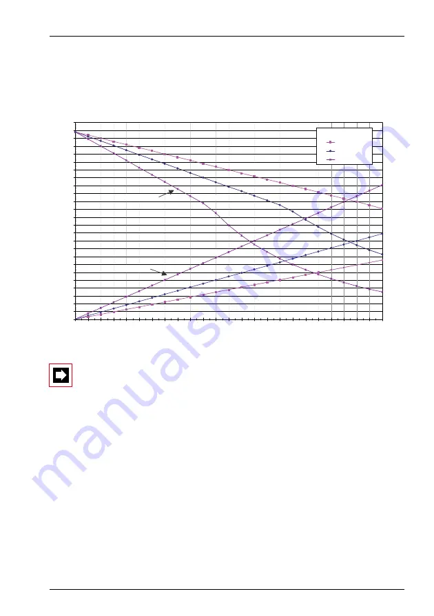
The diagram below shows the power available in relation to the line length and the
wire diameter. The table can then be used to determine the number and type of
terminals that can be connected to the AD2 bus under the given conditions. The
power available can also be calculated by measuring the loop resistance where the
wire diameter is known.
Fig. 60
Power available for terminals on the AD2 bus
Notes
– If another terminal is operated on the AD2 bus in addition to an
Aastra 5370 or Aastra 5380, at least one terminal must be powered by
a local power supply unit.
– An Aastra 5370 or Aastra 5380 with an Aastra M535 expansion keypad
always requires a power supply unit.
– An Aastra 5380 with 3 Aastra M530 expansion keypads always requires
a power supply unit. With 2 expansion keypads the use of power sup-
ply unit depends on the line length and the line cross-section.
500
600
700
800
900
1000
1100
1200
1300
1400
1500
1600
1700
1800
1900
2000
2100
2200
2300
2400
2500
2600
2700
2800
2900
3000
0
50
100
150
200
250
300
350
400
450
500
550
600
650
700
750
800
850
900
950
1000
1050
1100
1150
1200
Line lenght L [m]
d = 0.6 mm
d = 0.5 mm
d = 0.4 mm
d=0.4mm
500
480
460
440
420
400
380
360
340
320
300
280
260
240
220
200
180
160
140
120
100
80
60
40
20
0
d: Wire diameter
Power available for terminals on the
AD2 bus Pmax [mW]
Loop resistance R [Ohm]
d=0.4mm
d=0.5mm
d=0.6mm
d=0.6mm
d=0.5mm
Pmax [mW]
R [Ohm]


