Installation, Operation and Maintenance Manual
IO-70105 Rev 1, 1/2014
Surge Protective Devices
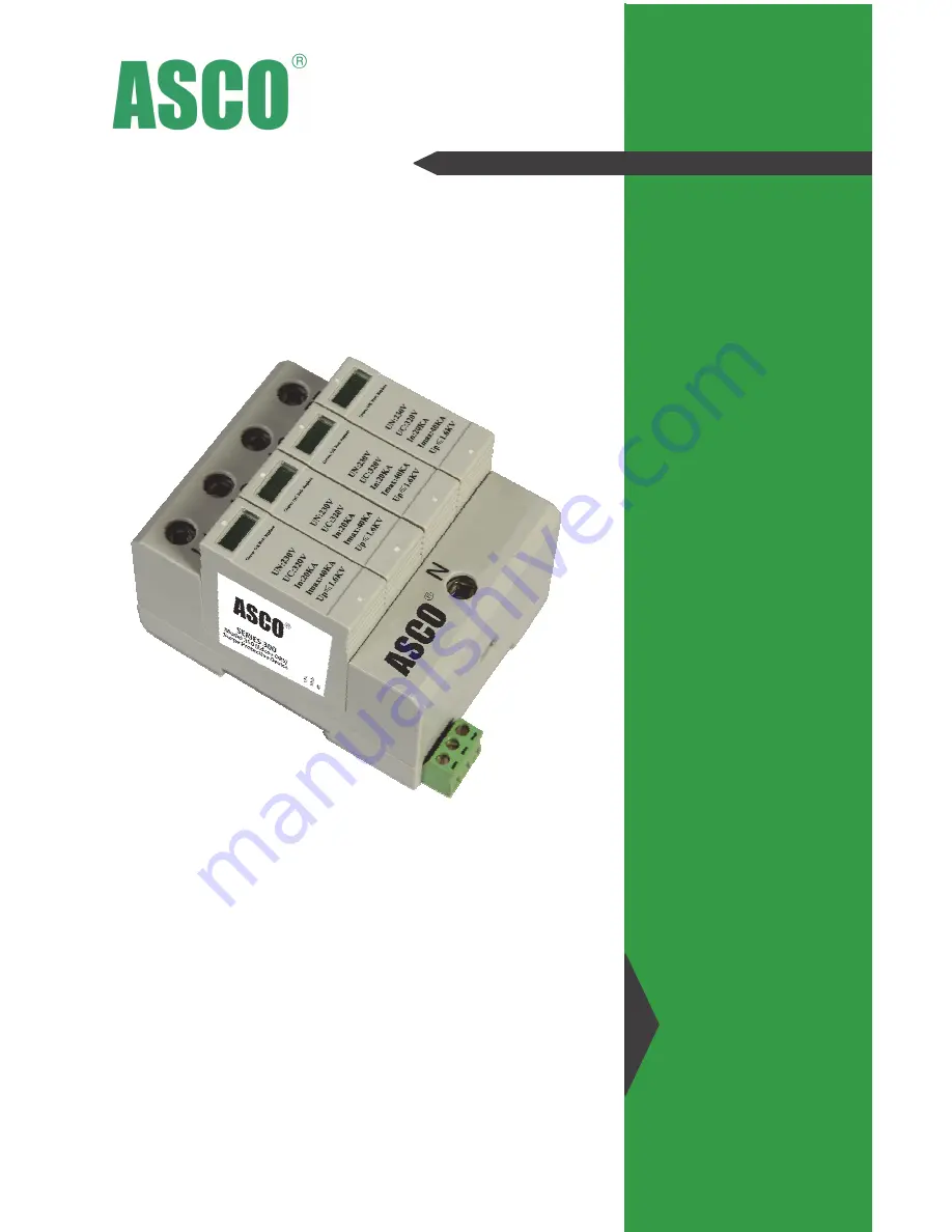
Model 310
Installation & Operation Manual
Model
310
Page 1: ...Installation Operation and Maintenance Manual IO 70105 Rev 1 1 2014 Surge Protective Devices Model 310 Installation Operation Manual Model 310 ...
Page 2: ...ld be used to improve performance of the SPD see Diagram 2 on page 3 Wire Sizing Routing Wire connection terminals accept wire with the cross sectional area of 6 35mm2 To reduce the wire impedance to surge currents all conducts should be twisted together and routed in the same conduit raceway All sharp bends in conductors should be avoided Over Current Protection External over current protection i...
Page 3: ...n A All Modes of Protection T Add N G Gas Tube Protection 12 Connection Type 1 Single Module 2 terminals 2 Two Modules 3 terminals 3 Three Modules 4 terminals 4 Four Modules 5 terminals 13 Monitoring Options F Mechanical Visual Flag 14 Enclosure N No Enclosure 15 UL 1449 Type N No UL 1449 approvals 16 Accessories 0 Standard X SPD with additional Options Accessories 1 2 3 4 5 6 7 8 9 10 11 12 13 14...
Page 4: ...5 E CustomerCare ASCO com While every precaution has been taken to ensure accuracy and completeness in this literature ASCO assumes no responsibility and disclaims all liability for damages resulting from use of this information or for any errors or omissions IO 80102 Rev 3 10 16 Printed in USA DIAGRAM 1 Standard Connection DIAGRAM 2 Kelvin Connection DIAGRAM 3 Remote Output ...