background image

Aruba 9240 Gateway

| Installation Guide

9240 Gateway |

11

USB Type-C Console Port

The 9240 is equipped with one USB type-C console port that provides console access for direct local 

access. If both USB and RJ-45 console ports are connected, the USB connection takes precedence 

over the RJ-45 console connection.

Using the USB Console Port

To use the USB type-C console port, follow these steps:
1. Download and install the USB driver file as follows:

a. Go to 

https://asp.arubanetworks.com

.

b. Click on the 

Software & Document 

tab.

c. Choose the 

Mobility Controller

.

d. Search “driver” in the search box.
e. In the search result, according to your operating system, choose the 

Windows Driver for USB 

Console port

 or 

MacBook Driver for USB Console port

 to download and install it to your PC. 

2. Use the USB type-C console cable, which is included in the package, to connect the gateway and 

your PC. 

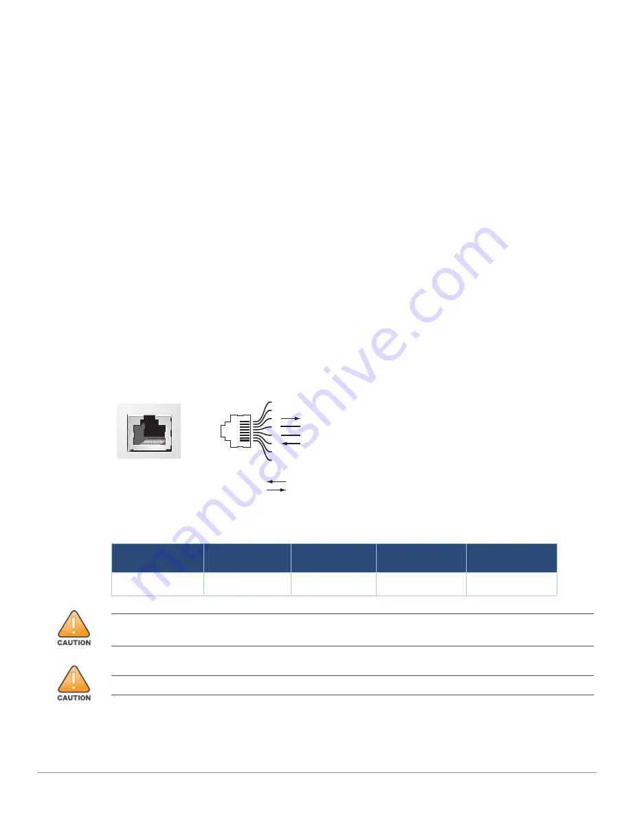
RJ-45 Console Port

The serial console port allows connecting a gateway to a terminal or a laptop for direct local 

management. This port is a RJ-45 female connector with the pin-out described in 

Figure 3

Figure 3  

Serial Console Port Pin-Out

Communication settings for the serial console port are indicated in 

Table 7


Table 7  

Console Terminal Settings

Baud Rate

Data Bits

Parity

Stop Bits

Flow Control

9600

8

None

1

None

Serial

Console Port

1

2

3

4

5

6

7

8

TxD

GND

RxD

RJ-45 Female

Pin-Out

Direction

Input

Output

GND

The CONSOLE port is compatible only with RS-232 devices. Non-RS-232 devices, such as APs, are not 
supported.

Do not connect the Console port to an Ethernet switch or a PoE power source. This may damage the gateway.

Summary of Contents for 9240

Page 1: ...Aruba 9240 Gateway Installation Guide...

Page 2: ...ses A complete machine readable copy of the source code corresponding to such code is available upon request This offer is valid to anyone in receipt of this information and shall expire three years f...

Page 3: ...xpansion Slot 12 Grounding Point 12 Fan Module 13 Hot Swapping 13 PSU Slot 0 13 Load Sharing 13 Redundancy 13 Hot Swapping 13 LED Indicators 14 PSU Slot 1 14 Chapter 2 Installation 15 Precautions 15 S...

Page 4: ...ting an LC Cable 24 Chapter 3 Specifications Safety and Compliance 25 9240 Specifications 25 Physical 25 Power Supply Specifications 25 Environmental 25 Regulatory Model Name 25 Safety and Regulatory...

Page 5: ...ty and regulatory compliance information Related Documentation The latest ArubaOS User Guide and ArubaOS CLI Reference Guide are required for the complete management of an Aruba gateway The latest doc...

Page 6: ...ncluding the original packing materials Use these materials to repack and return the unit to the supplier if needed 9240 Gateway Components This section introduces the different component and its loca...

Page 7: ...agement port RJ 45 used to connect to a separate management network 12 5 USB3 0 Interfaces 2 x USB3 0 interfaces USB storage device can be used to save and upload configurations 12 6 Power Status and...

Page 8: ...of the port The information displayed by this LED changes based on LCD s mode The LED behavior for each mode is described in Table 4 14 PSU Slot 1 Slot for additional power supply module 14 Table 3 A...

Page 9: ...of the LCD panel Enter Confirms and executes the action currently displayed on the LCD panel LCD Mode Menu The LCD mode menu includes four modes as shown in the following table Table 5 Power Status a...

Page 10: ...CLI commands host configure terminal host config lcd host lcd menu disable menu maintenance factory default halt system media eject reload system upgrade image upload config host lcd menu disable men...

Page 11: ...k Driver for USB Console port to download and install it to your PC 2 Use the USB type C console cable which is included in the package to connect the gateway and your PC RJ 45 Console Port The serial...

Page 12: ...y USB functions are controlled through the LCD panel on the front of the gateway For more information on the LCD panel and its functions see LCD Panel on page 9 Expansion Slot The expansion slot is re...

Page 13: ...r supply in PSU slot 0 and one filler panel in PSU slot 1 The gateway can operate with one or two active power supplies depending on the demands of your configuration The following sections describe f...

Page 14: ...power supply module as PSU slot 0 For more details see PSU Slot 0 on page 13 Never insert or remove the a power supply module while the power cord is connected to it Verify that cord has been disconn...

Page 15: ...o an electrical outlet Remove all rings jewelry and other potentially conductive material before working with this product Never insert foreign objects into the chassis the power supply or any other c...

Page 16: ...ning or air circulation equipment may be required Ample space For proper air circulation leave at least 10 cm 4 inches clearance all around the chassis Leave additional space in front and rear side of...

Page 17: ...he bracket to the gateway using the eight screws for the mount bracket four per bracket and a suitable screwdriver Figure 5 Attaching the Rack Mounting Brackets Standard 3 Mount the gateway within you...

Page 18: ...ver the mounting holes on either side of the gateway in the middle see Figure 7 2 Secure the bracket to the gateway using the eight screws for the mount bracket four per bracket and a suitable screwdr...

Page 19: ...quired Tools and Equipment Rubber Feet included in the kit Installation Steps 1 Attach the rubber feet to the bottom of the gateway see Figure 9 2 2 Leave a minimum of 10 cm 4 inches of space on the l...

Page 20: ...connected to the power supply module and an AC power outlet To connect the AC power cord to the 9240 gateway 1 Insert the coupler end of the AC power cord into the AC power connector on the power sup...

Page 21: ...ead screwdriver turn the screw counter clockwise until loose it cannot be removed completely b Use the fan module handle to pull the fan module out 2 Align the new fan module with opening in the gatew...

Page 22: ...r cord in the AC connector on the power supply module For more details see Connecting and Disconnecting the AC Power Cord on page 20 If you are adding an additional power supply module 1 Remove the fi...

Page 23: ...top side facing upward into a corresponding SFP28 port until a connection is made and an audible click is heard see Figure 13 Figure 13 Installing an SFP28 Removing an SFP28 Module To remove an SFP28...

Page 24: ...il a connection is made and an audible click is heard Figure 14 Connecting an LC Fiber Disconnecting an LC Cable To disconnect an LC fiber optic cable from an SFP28 module depress the transceiver hand...

Page 25: ...and Transportation Temperature Range 40 C to 70 C 40 F to 158 F Humidity Range 10 to 95 RH non condensing For additional specifications on this product please refer to the data sheet The data sheet c...

Page 26: ...sont conformes au x RSS s exempt s de licence d Innovation Sciences et D veloppement conomique Canada L op ration est soumise aux deux conditions suivantes 1 Cet appareil ne doit pas causer d interf...

Page 27: ...un quivalent recommand par le constructeur Mettre au rebut les batteries usag es conform ment aux unstruction du fabricant The battery supplied with this product may contain perchlorate material Speci...

Page 28: ...355 35 50 Proper Disposal of Aruba Equipment Waste of Electrical and Electronic Equipment Aruba a Hewlett Packard Enterprise company products at end of life are subject to separate collection and trea...

Page 29: ...Enterprise company products also comply with China environmental declaration requirements and are labeled with the EFUP 50 label shown at the left Hazardous Materials Declaration Hazardous Substances...

Reviews: