background image

2

|

Rev 01|October 2021

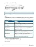
Figure 3

AP-655 Access Point Bottom View

1

E0 Ethernet Port

2

E1Ethernet Port

LED

The LED displays located on the front panel of the access point indicate the system status of the access point.

System Status LED

Color/State

Meaning

Off

Device Powered off

Green- solid

1

Device ready, fully functional, no network restrictions

Green- blinking

2

Device booting, not ready

Green- flashing off

3

Device ready, fully functional, either uplink negotiated in sub-optimal
speed (<1Gbps)

Green- flashing on

Device in deep-sleep mode

Amber- solid

Device ready, restricted power mode (limited PoE power available, or
IPM restrictions applied), no network restrictions

Amber- flashing off

Device ready, restricted power mode (limited PoE power available, or
IPM restrictions applied), uplink negotiated in sub-optimal speed
(<1Gbps)

Red

System error condition - Immediate attention required

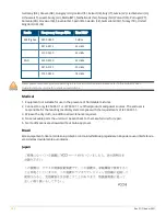
Table 1:

System Status LED

1. Blinking: one second on, one second off, 2 seconds cycle.
2. Flashing off: mostly on, fraction of a second off, 2 seconds cycle.
3. Flashing on: mostly off, fraction of a second on, 2 seconds cycle.

Radio Status LED

Summary of Contents for 650 SERIES

Page 1: ...aAOS or controllerless InstantOS network environments These access points support the 802 11ax standard in the 2 4GHz 5GHz and 6GHz bands with a 4x4 MIMO tri radio WI Fi 6E platform Additionally 650 S...

Page 2: ...negotiated in sub optimal speed 1Gbps Green flashing on Device in deep sleep mode Amber solid Device ready restricted power mode limited PoE power available or IPM restrictions applied no network res...

Page 3: ...nnector is located on the back of this device Use the proprietary AP CBL SERU cable or AP MOD SERU module sold separately for direct management of this device when connected to a serial terminal or la...

Page 4: ...modems and other peripherals When active this port can supply up to 5W 1A to a connected device Figure 6 650 Series USB Reset Button The reset button located on the bottom of the device can be used to...

Page 5: ...le 1 x 802 3at PoE enabled AP starts up in unrestricted mode but may dynamically apply restric tions depending on the PoE budget and actual power 1 x 802 3at PoE disabled Second other Ethernet port di...

Page 6: ...or obvious sources of interference These RF absorbers reflectors interference sources will impact RF propagation and should be accounted for during the planning phase and adjusted for in RF plan Use...

Page 7: ...d initial software configuration refer to theAP Software Quick Start Guide Aruba access points are classified as radio transmission devices and are subject to government regulations of the host countr...

Page 8: ...d automatically discontinue transmission in case of absence of information to transmit or operational failure Note that this is not intended to prohibit transmission of control or signaling informatio...

Page 9: ...RSS regulations Operation of this device is subject to the following two conditions 1 this device may not cause interference and 2 this device must accept any interference including interference that...

Page 10: ...bands Please refer to the ArubaOS User Guide Instant User Guide for details on restrictions Medical 1 Equipment not suitable for use in the presence of flammable mixtures 2 Connect to only IEC 60950...

Page 11: ...99 403 4677 050040 77 7 7 727 355 35 50 Ukraine Hereby Hewlett Packard Enterprise Company declares that the radio equipment type The Regulatory Model Number RMN for this device can be found in the Reg...

Page 12: ...ght Copyright 2021 Hewlett Packard Enterprise Development LP Open Source Code This product includes code licensed under the GNU General Public License the GNU Lesser General Public License and or cert...

Reviews: