ARTRAY ARTCAM-991SWIR-TEC-CL Setting Manual Download Page 14


© 2004 – 2021 ARTRAY Co., Ltd   

991SWIR-TEC-CL   

Camera Link


Setting Manual


14


Rev.1.00


6. 

Settings 

6.1. 

Preparation 

Before connecting camera to your PC, please install Camera Link frame grabber board, including driver 
and all the software necessary.   
In some cases, it is required to register the license of the product, please complete the registration 
before starting using the camera. 
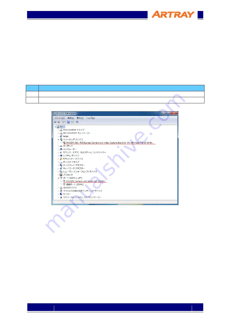
After installing, please open device manager to check if the grabber board is recognized normally. 
If you use our recommendations listed in table 2-2, the device names should be recognized as follows: 

Table 6-1: Devices Recognized 

No. 

Device 

PIXCI®EB1 PCI Express Camera Link Video Capture Board for Win XP/Vista/7/8/10-64bit 

PIXCI® Camera Link Serial Port (COM3

1

1

: Will be differ depending on systems. 


Figure 6-1: Sample of device manager 


6.2. 

Connect to Camera 

Please connect camera to the Camera Link frame grabber board with Camera Link cable. 
Before connect AC adapter to the camera, please start up the serial communication software. 
Command will be sent from the camera once it is connected to the power. 


Summary of Contents for ARTCAM-991SWIR-TEC-CL

Page 1: ...2004 2021 ARTRAY Co Ltd 991SWIR TEC CL Camera Link Setting Manual 1 Rev 1 00 ARTCAM 991SWIR TEC CL Camera Link Setting Manual rev 1 00...

Page 2: ...of the product 5 5 2 Communication Method 5 5 3 Command Format 5 5 4 List of Commands 6 5 5 Commands Details 7 5 5 1 Reset 7 5 5 2 Shutter 7 5 5 3 Gain 8 5 5 4 Temperature Control 8 5 5 5 Mirror 9 5 5...

Page 3: ...ure Serial Communication Software e g Tera Term PC Any which can adopt items mentioned above Camera Camera Link Cable The connector joining to camera should be SDR AC Adapter Please use the AC adapter...

Page 4: ...tified Grayscale 63 000MHz 3 2 Resolution The following table shows the maximum pixels of this camera Table 3 2 Resolution Model Horizontal Pixels Vertical Pixels ARTCAM 991SWIR TEC CL 640 512 4 Conne...

Page 5: ...Please be sure to use half width characters of ASCII code Table 5 2 Command Format 1 2 3 4 5 6 Format cmd opt val CR or LF or CR LF Details 1 One letter which represents the main purpose of the comman...

Page 6: ...ands Function cmd opt val Description Reset x Reset camera Shutter i v O Shutter speed setting Gain g v O Gain setting Temperature Control t v Sensor Temperature readout C vf FPGA Temperature readout...

Page 7: ...ra 1 2 Format x Details 1 x Reset 2 Line feed code Response Normal OK Abnormal NG Note Resets camera 5 5 2 Shutter Table 5 5 Shutter Speed Settings 1 2 3 4 5 6 Format i v val Details 1 i Shutter 2 Del...

Page 8: ...ntrol Table 5 7 Sensor Temperature Readout 1 2 3 4 Format t v Details 1 t Temperature control 2 Delimiter 3 v Option Sensor temperature readout 4 Line feed code Response Normal temperature Abnormal NG...

Page 9: ...e disable vertical mirror Table 5 10 Mirror horizontal 1 2 3 4 5 6 Format m H val Details 1 m Mirror 2 Delimiter 3 H Option Horizontal 4 Delimiter 5 0 disabled 1 enabled 6 Line feed code Response Norm...

Page 10: ...onse Normal Version 202012041730 example Abnormal NG Note To show firmware version 5 5 7 Peltier Table 5 13 Peltier ON 1 2 3 4 Format p y Details 1 p Peltier 2 Delimiter 3 y Peltier ON 4 Line feed cod...

Page 11: ...Format r p Details 1 r Capture mode 2 Delimiter 3 p Preview 4 Line feed code Response Normal OK Abnormal NG Note Configures capture as preview mode Table 5 13 Trigger Mode 1 2 3 4 Format r t Details...

Page 12: ...C LVAL High 320 clk D LVAL Low 115 clk E LVAL neg edge to FVAL neg edge 112 clk F FVAL Low 230517 clk G LVAL pos edge to DVAL pos edge 0 clk H DVAL High 320 clk Description Value Units A FVAL High 22...

Page 13: ...n 12 bits x 2 taps CL Port Bit Data 12bit Camera out 12 Bit A0 A 0 Tap1 A 11 0 A1 A 1 Tap2 B 11 0 A2 A 2 A3 A 3 A4 A 4 A5 A 5 A6 A 6 A7 A 7 B0 A 8 B1 A 9 B2 A 10 B3 A 11 B4 B 8 B5 B 9 B6 B 10 B7 B 11...

Page 14: ...er board is recognized normally If you use our recommendations listed in table 2 2 the device names should be recognized as follows Table 6 1 Devices Recognized No Device 1 PIXCI EB1 PCI Express Camer...

Page 15: ...dapter to the camera Figure 6 2 Icon of Tera Term After starting the software please choose the port correspondent with the name shown in device manager At the time this manual is made it is shown as...

Page 16: ...ther operation but not necessary to be Table 6 2 Communication Protocol Item Settings New line Receive CR New line Transmit CR LF Local echo Check the box Figure 6 5 To Set up Terminal on Tera Term Af...

Page 17: ...p the software you will see welcome message and license information If you have already registered please click OK directly If a warning or precaution concerning the license shows up you may not compl...

Page 18: ...lay area First please set communication settings choose Configure to set Camera Link configuration bit tap and color Please refer to table 3 1 to confirm the Camera Link format Figure 6 10 Configure S...

Page 19: ...of Camera Link in Timing Please refer to table 3 1 to confirm the Camera Link format Figure 6 12 Timing Settings The settings are finished now The image will be displayed either by clicking Live in Ca...

Reviews: