


FRU Installation
AXP640 Installation and Use (6806800M24F)
153
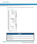
6. Grasp the handle on the module faceplate and remove the module from the shelf.
Apply steady pressure but do not force the module. If the SAM does not move, it
means the captive screw is not fully unscrewed. Unscrew until loose, and proceed
to remove the SAM.
6.3
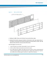
Unused Slots
All unused node or hub slots must be covered with filler blades. These filler blades ensure a
consistent airflow per slot whether or not the neighboring slot contains an AdvancedTCA
blade. There are filler blades sized for the front and for the RTM slots. When fillers are used, both
the front and RTM filler must be in place. Filler blades are available from Artesyn Embedded
Technologies.
All unused power bay slots should similarly be filled with slot fillers when not in use. Additional
power bay slot fillers are available from Artesyn.
6.4
Installing Power Entry Modules
The AXP640 shelf supports two Power Entry Modules (PEMs). Since the shelf is equipped with
a redundant power distribution system, the removal of a single PEM does not interrupt system
operation. PEMs are accessible from the rear of the shelf. Each PEM has EMI gaskets on all sides
of the module that provide EMI shielding.
The following instructions describe how to replace a power entry module. For further
information on power entry modules, refer to
6.4.1
Tool You Will Need
Standard #2 Phillips-head screwdriver
6.4.2
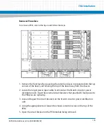
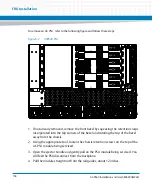
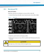
Removing the PEM
When replacing a PEM, make sure you have a replacement PEM available. PEMs are accessible
from the front of the shelf, and does not require removal of the shelf power wiring.
Summary of Contents for AXP640
Page 1: ...AXP640 Installation and Use P N 6806800M24F May 2014 ...
Page 8: ...AXP640 Installation and Use 6806800M24F Contents 8 Contents Contents ...
Page 10: ...AXP640 Installation and Use 6806800M24F 10 List of Tables ...
Page 50: ...Platform Architecture AXP640 Installation and Use 6806800M24F 50 ...
Page 70: ...AXP640 Shelf Description AXP640 Installation and Use 6806800M24F 70 Figure 2 14 AC Inlet 220V ...
Page 101: ...Site Preparation AXP640 Installation and Use 6806800M24F 101 Figure 3 13 Planning Checklist 2 ...
Page 102: ...Site Preparation AXP640 Installation and Use 6806800M24F 102 ...
Page 112: ...AXP640 Operations AXP640 Installation and Use 6806800M24F 112 ...
Page 136: ...AXP640 Shelf Installation AXP640 Installation and Use 6806800M24F 136 ...
Page 164: ...FRU Installation AXP640 Installation and Use 6806800M24F 164 ...
Page 186: ...Shelf Management Alarm Module AXP640 Installation and Use 6806800M24F 186 ...
Page 189: ......