


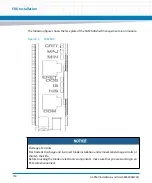


FRU Installation
AXP640 Installation and Use (6806800M24F)
143
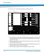
Switched off blue LEDs indicate that the payload of the respective blade or RTM has
become active.
13. Plug interface cable into face plate connectors, if applicable.
6.2.1.2
Removing the RTM
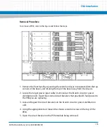
Removal Procedure
The following procedure describes the removal of the RTM. It assumes that your system is
powered. If your system is unpowered, you can disregard the blue LED and thus skip the
respective step. In this case it is a purely mechanical procedure.
Damage of RTM and Front Blade
Removing the RTM from the system while the payload of the front blade is powered up may
damage the front blade and RTM.
Whenever removing the RTM from the system, you have to power down the payload of the
front blade first.
Summary of Contents for AXP640
Page 1: ...AXP640 Installation and Use P N 6806800M24F May 2014 ...
Page 8: ...AXP640 Installation and Use 6806800M24F Contents 8 Contents Contents ...
Page 10: ...AXP640 Installation and Use 6806800M24F 10 List of Tables ...
Page 50: ...Platform Architecture AXP640 Installation and Use 6806800M24F 50 ...
Page 70: ...AXP640 Shelf Description AXP640 Installation and Use 6806800M24F 70 Figure 2 14 AC Inlet 220V ...
Page 101: ...Site Preparation AXP640 Installation and Use 6806800M24F 101 Figure 3 13 Planning Checklist 2 ...
Page 102: ...Site Preparation AXP640 Installation and Use 6806800M24F 102 ...
Page 112: ...AXP640 Operations AXP640 Installation and Use 6806800M24F 112 ...
Page 136: ...AXP640 Shelf Installation AXP640 Installation and Use 6806800M24F 136 ...
Page 164: ...FRU Installation AXP640 Installation and Use 6806800M24F 164 ...
Page 186: ...Shelf Management Alarm Module AXP640 Installation and Use 6806800M24F 186 ...
Page 189: ......