


AXP640 Operations
AXP640 Installation and Use (6806800M24F)
107
4.5.1
Description
The AXP640 has PICMG 3.0 compliant, dual DC PEMs and is rated for nominal -48VDC to
-60VDC. The PEMs plug directly into an intermediate power board that delivers power to the
main backplane, delivers power to the backplane. Each input is rated for 60 amps. The 60 amp
feed powers six AdvancedTCA slots, SAMs, and FTMs.
Power is introduced to the PEM using a DC power cable attached to the terminal blocks on the
rear of the chassis (power input cable and return cable). The terminal block consists of a dual
stud connection which prevents the power cables from rotating and provides secure contacts
for the cable lug. There is a plastic cover that protects the cable connections.
4.5.2
IPMC Circuitry
Each PEM is capable of monitoring voltage and circuit breaker status. The PEMs are loaded with
the AdvancedTCA IPMC firmware. Preprogrammed FRU and Sensor Data Record (SDR)
information reside on the PEM and is accessible from the SAM through the IPMB ports of the
PEM. In addition, the IPMC monitoring functions include digital inputs to detect circuit breaker
trips, voltage sensors to detect backplane voltages, current sensors to detect current to the
backplane, and on-board circuitry to detect failures on the PEM. The PEMs are managed by the
Removing power to these components cannot be accomplished by turning the PEM's circuit
breakers to the OFF position. The PEMs remain powered until the -48VDC power to each
terminal block on the rear of the chassis is removed. Make sure you disconnect the power
at the external source before removing the PEM from the shelf.
The DC power inputs must only be attached to approved Telephone Network Voltage (TNV)
or Safety Extra Low Voltage (SELV) branch circuits. Branch circuits must comply with all
requirements called for in these safety standards: IEC 60950, EN 60950, CAN/CSA-C22.2 No.
60950. Attaching inputs to non-TNV/SELV approved power sources will cause the system to
fail compliance with safety regulations.
Summary of Contents for AXP640
Page 1: ...AXP640 Installation and Use P N 6806800M24F May 2014 ...
Page 8: ...AXP640 Installation and Use 6806800M24F Contents 8 Contents Contents ...
Page 10: ...AXP640 Installation and Use 6806800M24F 10 List of Tables ...
Page 50: ...Platform Architecture AXP640 Installation and Use 6806800M24F 50 ...
Page 70: ...AXP640 Shelf Description AXP640 Installation and Use 6806800M24F 70 Figure 2 14 AC Inlet 220V ...
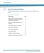
Page 101: ...Site Preparation AXP640 Installation and Use 6806800M24F 101 Figure 3 13 Planning Checklist 2 ...
Page 102: ...Site Preparation AXP640 Installation and Use 6806800M24F 102 ...
Page 112: ...AXP640 Operations AXP640 Installation and Use 6806800M24F 112 ...
Page 136: ...AXP640 Shelf Installation AXP640 Installation and Use 6806800M24F 136 ...
Page 164: ...FRU Installation AXP640 Installation and Use 6806800M24F 164 ...
Page 186: ...Shelf Management Alarm Module AXP640 Installation and Use 6806800M24F 186 ...
Page 189: ......