


AT32F413
Series Reference Manual
2022.06.27
Page 277
Rev 2.00
19.5 Master/Slave mode
If Master/Slave mode is enabled, the master is triggered to work with the slave to do the channel
conversion. The ADC_ODT register is used as a single interface obtaining the ordinary channel
converted data of master/salve ADC.
In this mode, ADC1 acts as a master while ADC2 as a slave.
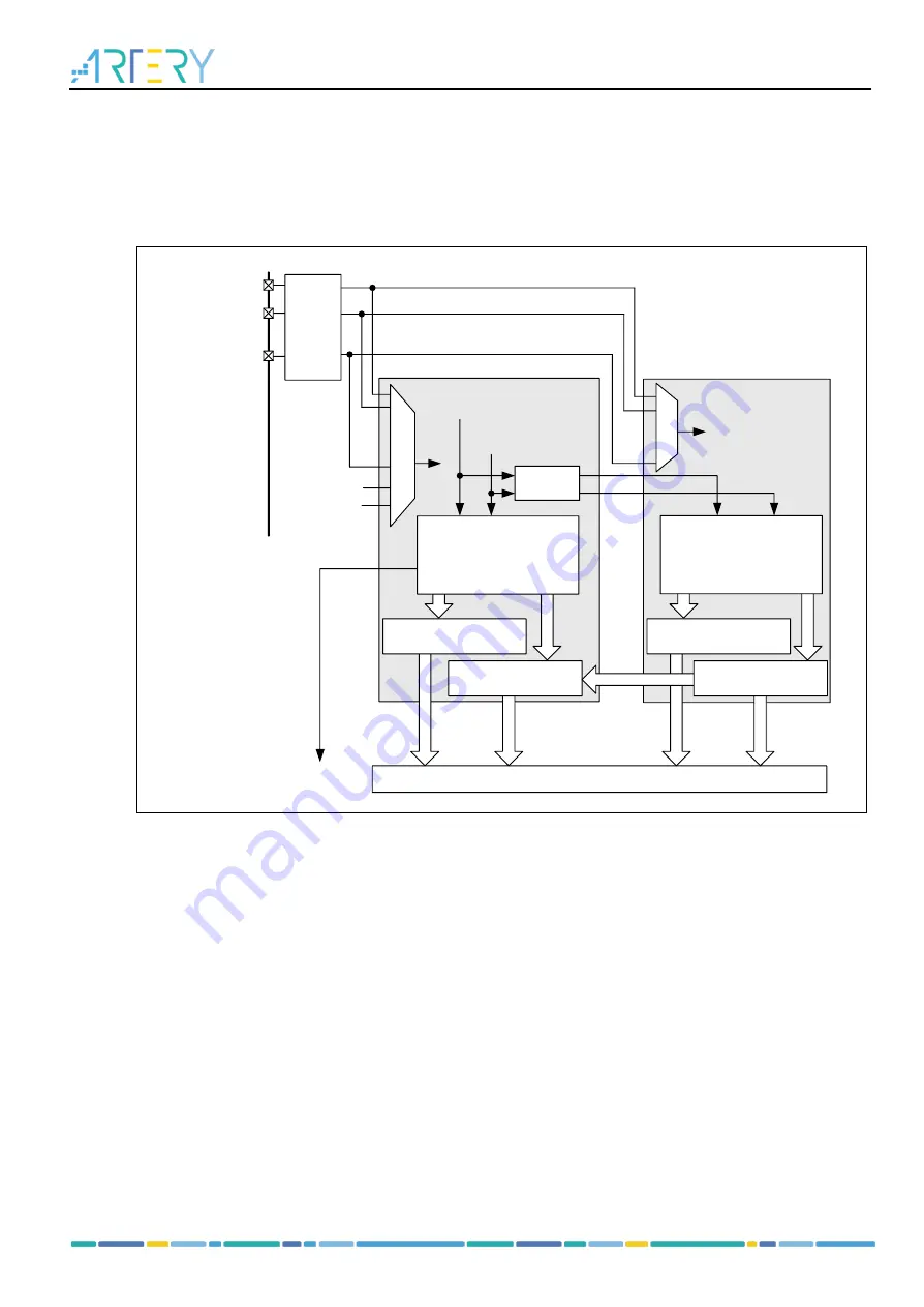
Figure 19-9
Block diagram of master/salve mode
Address/Data bus
ADCx_IN1
ADCx_IN0
ADCx_IN15
...
Temp.sensor
INTRV
V
Ordinary
conversion start
Preempted
conversion start
...
...
ADC1
ADC2
GPIO
Channel and
data
management
Channel and
data
management
Slave
controller
Preempted data register
(4*16 bits)
Ordinary data register
(32 bits)
Preempted data register
(4*16 bits)
Ordinary data register
(16 bits)
DMA request
19.5.1 Data management
In Master/Slave mode, the data of ordinary channels is also stored in the ADC_ODT register of ADC1.
As long as the OCDMAEN is set in the ADC1_CTRL2 register, the ADC1 DMA channel is used to
generate a DMA request each time when the data is ready.
19.5.2 Regular simultaneous mode
Regular group simultaneous conversion mode
MSSEL bit in the ADC_CTRL1 register is used to select regular group simultaneous conversion mode.
When this mode is enabled, is is possible to trigger the regular group of the master to enable
simultaneous conversion of the regular group by master and slave. In this mode, it is required to
configure the same sampling time and the same sequence length for the master and slave to avoid the
loss of data due to the lack of synchronization.
shows an example of the regular simultaneous mode
Note: The same channel is not allowed to be sampled by several ADCs simultaneously. Do not put
the same channel in the same sequence location of different ADCs.