SXU-1 Single Axis Unit
Date: 05 February 2014
I n s t r u c t i o n M a n u a l
Page 1: ...SXU 1 Single Axis Unit Date 05 February 2014 I n s t r u c t i o n M a n u a l ...
Page 2: ...ifications excepted ALEXA and ALEXA XT are trademarks or registered trademarks of Arnold Richter Cine Technik GmbH Co Betriebs KG All other brands or products are trademarks or registered trademarks of their respective holders and should be treated as such Original version For further assistance ARRI Cine Video Geräte Gesellschaft m b H Pottendorferstraße 25 27 3 1 A 1120 Vienna Austria E mail ser...
Page 3: ...ation setups 11 4 1 Wireless via white radio 11 4 2 Wired via LCS 12 5 Power supply 13 5 1 Rechargeable battery 13 5 2 AC power grid 14 5 3 LCS hardwire 15 6 Prior to operation 16 6 1 Before each switch on 16 6 2 After each change of lens 16 6 3 Switching on and initialization 16 6 4 Selecting a radio channel 18 6 5 Switching the radio off on 19 6 6 Selecting a lens axis 20 6 7 Calibrating to lens...
Page 4: ...ance 31 9 1 Firmware update 31 9 2 System information 33 10 Storage shipment disposal 34 11 Order numbers 35 11 1 Included accessories 35 11 2 Optional accessories 35 11 3 Recommended charger and battery 35 11 4 LCS cables 35 12 Appendix 36 12 1 LCS connector pin out 36 12 2 Dimensions and weight 36 12 3 Electrical data 36 12 4 ARRI white radio channels ISM B 37 12 5 Declarations of conformity 38 ...
Page 5: ...void possible injury or death DANGER Indicates an imminent hazardous situation which if not avoided will result in death or serious injury NOTICE Explains practices not related to physical injury The safety alert symbol is not used with this signal word Note Provides additional information to clarify or simplify a procedure 1 2 Vital precautions NOTICE Read and follow all instructions before using...
Page 6: ...s Every user should be trained according to ARRI guidelines The SXU 1 is a single axis hand unit solely and exclusively for iris focus or zoom control Wireless via ARRI white radio modem see p 11 Wired via ARRI Lens Control System LCS Note For use with other systems consult the respective manufacturer Never use the product for any other purpose Always follow the valid instructions and system requi...
Page 7: ...delivery A complete delivery includes Single Axis Unit SXU 1 Shoulder strap Plain white marking ring Instruction manual Original packaging For scope of warranty please ask your local ARRI representative ARRI is not liable for consequences from inadequate shipment improper use or third party products For spare parts and additional accessories see p 35 ...
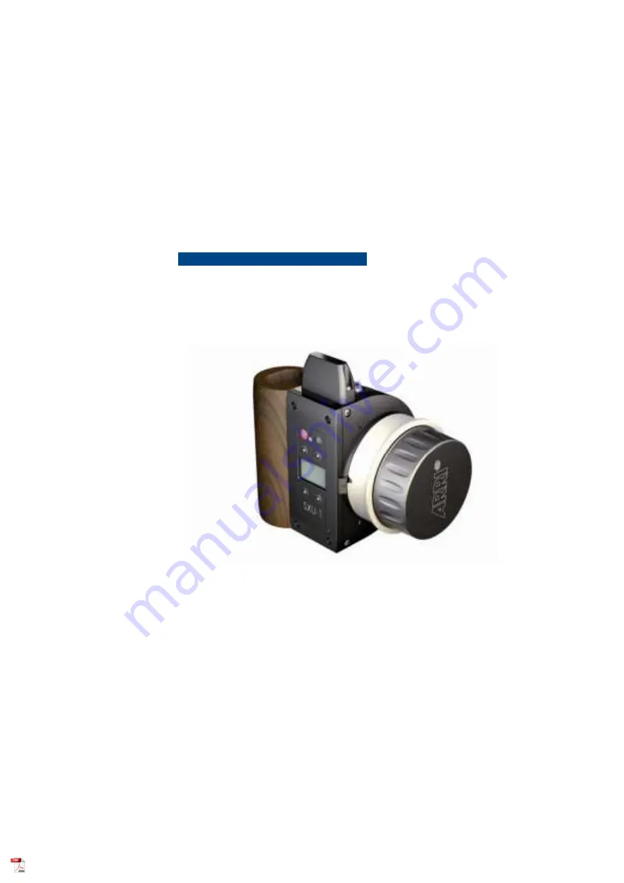
Page 8: ...is compatible with ALEXA XT Plus Studio models or with other cameras via the Universal Motor Controller UMC 3A 1 Control panel 7 White radio marker 2 Internal antenna 8 Grip 3 Plain marking ring 9 Finger rest 4 Check mark with nut 10 Product ID labels 5 Control knob 11 Eyelet for shoulder strap 6 LCS socket 12 Battery compartment ...
Page 9: ...e product s back FCC ID and IC numbers are on the CE conformity label 1 3 2 Control knob NOTICE Motors can be rigged either left or right of a lens Correct control knob operation requires a properly set lens motor direction see p 23 1 Turn the control knob to adjust focus iris or zoom setting ...
Page 10: ...button 6 Display 3 4 Control display 1 Upper navigation buttons 5 Connectivity status 2 Upper navigation info 6 Battery status 3 Lower navigation info 7 Preset lens axis 4 Lower navigation buttons 8 Radio channel number When navigating the home screen will change to subscreens of a different structure The navigation info for each button may change ...
Page 11: ...e camera or motor controller 4 1 Wireless via white radio For wireless operation you can combine up to three SXU 1 per camera or motor controller Sync cables allow a 3D operation Please consult your camera or controller manuals Or ask your ARRI partner NOTICE You cannot address two cameras simultaneously on the same radio channel ...
Page 12: ...t 4 2 Wired via LCS For wired operation maximum LCS cable length is 75 m 250 ft Power is supplied via the camera or motor controller NOTICE LCS connection automatically disables the SXU 1 s white radio and distributed control ...
Page 13: ...eries should not be disposed of in domestic waste Always dispose them according to valid local regulations and the information in the battery manual NOTICE Normal charging is usually completed when the charge LED on the battery charger goes out for details see battery and charger manuals 1 Charge battery according to battery and charger manuals 2 Unlatch 1 and remove empty battery 2 3 Insert full ...
Page 14: ...to humidity Never disassemble Via five different adapters the optional Hand Unit AC Power Supply connects the product to AC grids worldwide 1 Click adapter 1 onto power pack 2 2 Connect power pack to LCS socket 3 and AC grid 3 Product is now ready to switch on NOTICE Battery charging is not possible via the product AC power supply always entails wireless white radio operation ...
Page 15: ... 3 LCS hardwire 1 Connect product 1 to camera 2 via a standard LCS cable maximum length 75 m 250 ft 2 Product is now supplied with power control lines and ready to switch on NOTICE Battery charging is not possible via the product ...
Page 16: ...atically prompt you Calibrate motor now If not Check connection to camera For calibration see p 21 If necessary Change motor direction left right see p 23 Manually recalibrate see p 21 Change motor torque 1 to 4 see p 22 6 3 Switching on and initialization NOTICE A full initializon always ends with a full automatic calibration If not Connect product properly to camera Check for Correct white radio...
Page 17: ... button 1 3 Product initializes Display blinks init 2 4 Check product connectivity 1 Ready to connect but not yet connected If 1 blinks init Product is still initializing 2 White radio connected If 2 is blank White radio is off or replaced by an LCS connection or current channel is occupied otherwise ...
Page 18: ... end position 7 CAL reappears solid initialization complete 6 4 Selecting a radio channel NOTICE Never select a frequency that will interfere with other radio setups When initially selecting a radio channel do so via the camera receiver not via the product 1 Press MENU A 2 Menu opens on Radio Channel B 3 Press ENTER ...
Page 19: ... DOWN to select new channel for frequencies see p 37 or to switch white radio OFF 6 Confirm with SET D 7 Exit with HOME 6 5 Switching the radio off on 1 Enter Radio Channel see A to C above 2 To deactivate Scroll UP until OFF and press SET E 3 To re activate Press ON then SET 4 Exit with HOME ...
Page 20: ...ens C 6 Check preset lens axis n a indicates non availability 7 Scroll UP or DOWN to select Focus Iris Zoom or off D Note Select off to deactivate all lens axes 8 Confirm with SET all other axis are off now 9 Exit with HOME NOTICE Deactivating all lens axes with off helps you freeze a lens in its position and avoid accidental lens action ...
Page 21: ...direction To avoid damage always calibrate motors to a new lens 1 Press CAL A for at least three seconds 2 Display will count down to zero B 3 CAL blinks up CALIBRATING C 4 Lens motor moves lens ring from one end to the other 5 CAL D reappears solid 6 Calibration complete NOTICE To interrupt calibration release CAL button during count down ...
Page 22: ... Rule of thumb Small lens small torque Always increase the torque in small steps 1 Press MENU A 2 Menu opens B 3 Scroll DOWN until Motor Torque 4 Press ENTER 5 With UP or DOWN C select iris focus or zoom motor n a means motor not connected 6 Press CHANGE for each selection 7 With UP or DOWN D select a torque 4 max 8 Confirm and exit with HOME ...
Page 23: ...the lens motor direction 1 Press MENU A 2 Menu opens B 3 Scroll DOWN until Motor Direction 4 Press ENTER 5 With UP or DOWN C select focus iris or zoom motor 6 Press CHANGE for each selection 7 Confirm with SET D 8 Confirm and exit with HOME ...
Page 24: ...ons see p 16 7 1 Changing the backlight The display and control knob backlight can be dimmed to a preset maximum You can toggle between two modes AUTO Backlight automatically on off via sensor FIX Steady backlight 1 Press MENU A 2 Menu opens B 3 Scroll DOWN until Backlight 4 Press ENTER ...
Page 25: ...e onto FIX D 7 Scroll UP or DOWN for backlight intensity 0 off 8 Confirm and exit with HOME 7 2 Limiting the motor range Limiting the motor range allows a more sensitive lens control 1 With control knob A turn lens axis to desired start position 2 Press LIMIT once B until blinking ...
Page 26: ...et 6 To reset Press LIMIT D again NOTICE To set motor limits you can also keep LIMIT pressed from start to end position Motor and knob limits can be combined 7 3 Limiting the control knob range Limiting the control knob range allows faster lens reactions 1 With control knob A turn lens axis to desired start position 2 Press K LIM once B until blinking ...
Page 27: ...6 To reset Press K LIM D again NOTICE To set control knob limits you can also keep K LIM pressed from start to end position Knob and motor limits can be combined 7 4 Recording 1 Check LED 1 for camera standby Solid green Ready to roll Flashes red Pre recording Solid red Recording Flashes green and red Error Out Disconnected 2 Press REC 1 to start or stop ...
Page 28: ...it 7 5 Switching off 1 Press power button 1 for at least three seconds 2 Display 2 will count down to zero and go out 3 Product is now switched off NOTICE To interrupt switch off simply release power button during count down ...
Page 29: ...ing rings allow you to scale the control knob with simple board markers You can also change the rings 1 Pull off old marking ring 1 1 New ring must align properly 2 see detail and snap audibly 8 2 Shoulder strap 1 Insert the shoulder strap s snap hook 1 into bottom eyelet 2 ...
Page 30: ...30 SXU 1 Single Axis Unit 8 3 Optional rigger grip 1 With a 3 mm Allen key unscrew standard grip 1 Note Screws are secured from falling into the grip 1 Attach rigger grip 2 2 Product is now ready to rig ...
Page 31: ...hock or aggressive substances 9 1 Firmware update NOTICE Update the product consistently Prior to update battery must be fully charged see p 13 Never press any button while update is running Required tools not included 3 mm Allen key Access to www arri de pca sxu 1 SD SDHC memory card FAT 1 Go to download area at www arri de pca sxu 1 2 Download zip file containing SXU 1 upd 3 Unzip file 4 Copy SX...
Page 32: ... MENU A 9 Menu opens B 10 Scroll DOWN until Firmware 11 Press ENTER 12 Update information appears C 13 Press both UPDATE keys simultaneously 14 LED flashes red and green update running 15 LED stops product restarts D 16 Update complete ...
Page 33: ...SXU 1 Single Axis Unit 33 17 Switch off product 18 Remove SD card 2 19 Reattach grip 1 9 2 System information 1 Press MENU A 2 Menu opens B 3 Scroll UP or DOWN until System Info 4 Press ENTER ...
Page 34: ...n appears C 6 For menu Go BACK 7 Exit via HOME 10 Storage shipment disposal NOTICE Always store ship and dispose of the product according to local regulations ARRI is not liable for consequences arising from inadequate storage shipment or disposal ...
Page 35: ...2 0000425 Hand Unit AC Power Supply HPS 1 K2 0000849 Rigger Grip K2 0000848 Calibrating Ring 11 3 Recommended charger and battery K2 47851 0 SONY NP FM 500H Li Ion Battery K2 47852 0 SONY BC VM10 Charger 05 20369 0 Power Cord UK 05 20370 0 Power Cord US 05 20368 0 Power Cord EU 11 4 LCS cables K4 41395 0 K LC Z1 S LCS Cable 3 5 m 11 ft K4 41397 0 K LC M1 Sp S LCS Spiral Cable K2 41389 0 LC E1 LCS ...
Page 36: ... 148 mm H 139 mm D 89 mm Weight without straps and battery 592 g 20 9 oz 12 3 Electrical data AC power input 100 to 240 V 50 to 60 Hz 300 mA DC output no battery charge 12 V 6 W max Battery power supply 7 2 V Li Ion 11 8 Wh LCS power supply 10 4 to 34 V DC Power consumption 220 mA at 7 6 V 70 mA at 24 V Operating temperature 20 to 50 C 4 to 122 F ...
Page 37: ...SXU 1 Single Axis Unit 37 12 4 ARRI white radio channels ISM B 0 2 410 GHz 1 2 415 GHz 2 2 430 GHz 3 2 435 GHz 4 2 450 GHz 5 2 455 GHz 6 2 470 GHz 7 2 475 GHz ...
Page 38: ...010 EN 55103 2 2009 EN 301 489 1 2011 EN 301 489 17 2012 EN 62479 2010 EN 60950 1 2006 A11 2009 A12 2011 A1 2010 AC 2011 DIN EN 50581 2013 02 Munich 06 Feb 2014 Signature in the original W Trauninger J Althammer FCC Compliance Statement This equipment has been tested and found to comply with the limits for a Class A digital device pursuant to Part 15 of the FCC Rules These limits are designed to p...
Page 39: ...nforme à la norme NMB 003 du Canada This device complies with RSS 210 of Industry Canada This Class A device meets all the requirements of the Canadian interference causing equipment regulations Cet appareil numérique de la Classe A respecte toutes les exigences du Réglement sur le matériel brouilleur du Canada Contains Transceiver Module IC ID 9482A EMIP100 ...
Page 40: ...For further assistance ARRI Cine Video Geräte Gesellschaft m b H Pottendorferstraße 25 27 3 1 A 1120 Vienna Austria E mail service arri com www arri com ...