background image

           Wheels, Axles & Chains

Argo Service Manual    

WA-14


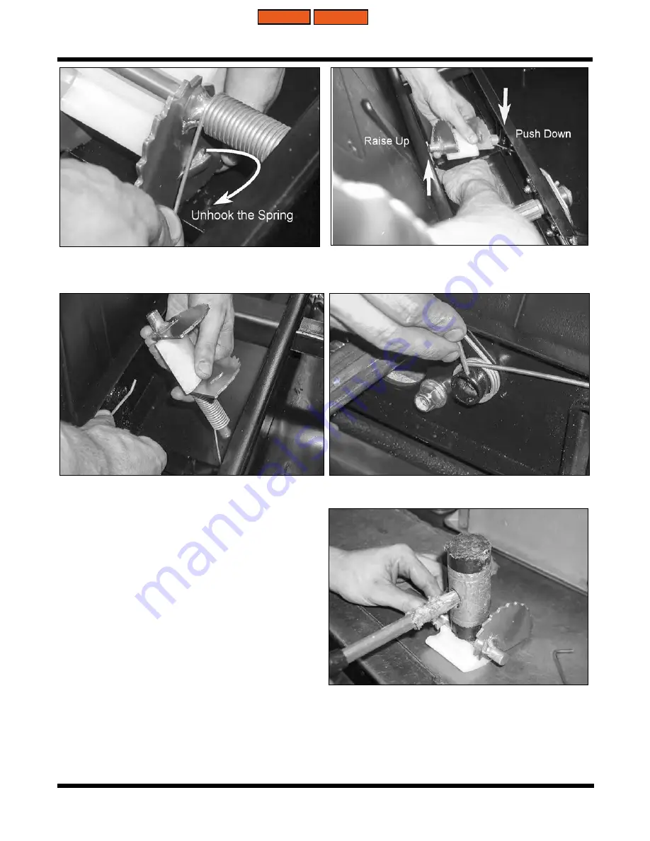
3.  Slip the one torsion spring off the cam, and remove the second torsion spring from the 

frame assembly by removing the cotter pin that secures it. 

Assembling the Chain Tensioner System (Semi-Self Adjust)

1.  Place the tensioner block onto a work-

bench and position the slider block over 

the shaft of the assembly.

2.  With a soft faced mallet, tap the slider 

block to snap it on to the shaft. 

3.  Slip a torsion spring over the welded  

bushing in the frame, and secure with a 

cotter pin. 

4.  Slip the second torsion spring on to the 

shaft of the tensioner cam assembly.


MAIN INDEX

WA INDEX

Summary of Contents for All 6X6

Page 1: ...Printed in Canada 2022 01 01 All 8X8 MODELS All 6X6 MODELS SERVICE MANUAL 2022...

Page 2: ......

Page 3: ...ed by a 2 letter designation Find the section you want in the guide on this page and then turn to the Table of Contents on page 1 of that section Each section begins with general information for servi...

Page 4: ...Argo Service Manual Ontario Drive Gear Limited www argoutv com PH 519 662 2840 FAX 519 662 2421...

Page 5: ...SERVICE INSTRUCTION GI 4 ARGO MODEL SPECIFICATIONS GI 5 IDENTIFICATION AND LOCATION OF CONTROLS AURORA GI 10 IDENTIFICATION AND LOCATION OF CONTROLAS FRONTIER GI 11 INFORMATION LABELS 8X8 GI 12 INFORM...

Page 6: ...This ARGO Service Manual provides information on maintenance procedures service operations and on the removal disassembly reassembly and installation of components parts and assemblies All informatio...

Page 7: ...NING Warning text warns the user about potential hazards that can result in personal injury or death Cautions are identified in the text by the following symbol CAUTION Caution text contains cautions...

Page 8: ...ice Manual for 1987 Models Part Number 673 02 Service Manual Supplement for NKB Models 1988 Part Number 673 04 1 Service Manual for Models from 1992 2002 Part Number 673 11 Service Manual for Models f...

Page 9: ...ing amps at 0 F 20 50 Amp charging system electronic ignition 12 volt D C AGM battery 385 cold cranking amps at 0 F 20 50 Amp charg ing system electronic ignition Load Capacity Land 1100lbs 499kg 1100...

Page 10: ...12 volt D C AGM battery 385 cold cranking amps at 0 F 20 50 Amp charging system electronic ignition Load Capacity Land 1000lbs 454kg 960lbs 435 kg 730lbs 331kg 1080lbs 490kg Water 800lbs 363kg 760lbs...

Page 11: ...chain Electrical 12 volt D C AGM battery 385 cold cranking amps at 0 F 20 50 Amp charging system elec tronic ignition Load Capacity Land 850lbs 385 kg 980lbs 444 kg 1060lbs 481 kg Water 650lbs 295 kg...

Page 12: ...ith hydraulic disc stopping brakes Drive Chains Single RC60 Roller Chain Electrical 12 volt D C AGM battery 385 cold cranking amps at 0 F 20A charging system Load Capacity Land 254 kg 560 lbs 254 kg 5...

Page 13: ...with hydraulic disc stopping brakes Drive Chains Double RC50 Single RC60 Roller Chain Electrical 12 volt D C battery 435 cold cranking amps at 0 F 20A charging system Load Capacity Land 206 kg 455 lbs...

Page 14: ...General Information Argo Service Manual GI 10 Ontario Drive Gear Limited www argoutv com PH 519 662 2840 FAX 519 662 2421 IDENTIFICATION AND LOCATION OF CONTROLS AURORA GI INDEX MAIN INDEX...

Page 15: ...ce Manual GI 11 Ontario Drive Gear Limited www argoutv com PH 519 662 2840 FAX 519 662 2421 IDENTIFICATION AND LOCATION OF CONTROLS FRONTIER Figure 1 Frontier 700 EFI Figure 2 Frontier 600 650 Briggs...

Page 16: ...indicate operating hazards and provide special operating instructions Information about the use of the holding brake system the use of the vehicle in water correct fuelling procedures and placement of...

Page 17: ...abels on all models which indicate operating hazards and provide special operating instructions Information about the use of the holding brake system the use of the vehicle in water correct fuelling p...

Page 18: ...344 51 81 124 238 423 191 381 58 91 140 280 490 Min 93 192 28 45 69 100 138 245 90 180 27 43 66 94 132 231 Max 144 251 37 59 90 130 180 320 131 261 40 62 96 137 192 336 Min 76 157 23 37 57 82 113 200...

Page 19: ...ated 94 194 29 46 70 134 238 107 215 32 51 79 158 275 Anti Seize Threadlocker or Plain Steel 107 219 32 52 80 152 270 122 243 37 58 89 179 312 Zinc Plated 125 258 38 61 93 179 317 143 286 44 68 105 21...

Page 20: ...9 267 Zinc Plated 92 225 37 65 104 161 222 314 Lubricated 100 242 40 70 111 173 239 337 Anti Seize Threadlocker or Plain Steel 113 274 45 79 126 196 270 382 Zinc Plated 133 323 53 93 148 230 318 449 L...

Page 21: ...3 142 200 Zinc Plated 69 169 28 49 78 121 167 236 Lubricated 75 182 30 53 83 130 179 253 Anti Seize Threadlocker or Plain Steel 85 206 34 59 95 147 203 287 Zinc Plated 100 242 40 70 111 173 239 337 Lu...

Page 22: ...on L C Models Check Fuel Level Check Tire Inflation Check Finger Throttle Operation Check Handlebar Travel Check Engine Intake Exhaust For Obstructions Change That The Drain Plugs Are In Place Check E...

Page 23: ...tle Operation Check Handle Bar Travel Check Engine Intake Exhaust for Obstructions Check that the drain plugs are in place Check Engine Oil Level Change Engine Oil And Filter Check Transmission Oil Le...

Page 24: ...Output Shaft Puller 4 658 07 Bearing Installer 101 15 Bearing 5 658 16 Right Angle Grease Fitting 6 638 02 Oil Change Pump 7 19352 Tang Bending Tool 7 193889 Tiny Tach 8 19545 Leak Down Tester Briggs...

Page 25: ...General Information Argo Service Manual GI 21 Ontario Drive Gear Limited www argoutv com PH 519 662 2840 FAX 519 662 2421 5 6 7 8 9 10 GI INDEX MAIN INDEX...

Page 26: ...General Information Argo Service Manual GI 22 Ontario Drive Gear Limited www argoutv com PH 519 662 2840 FAX 519 662 2421 11 12 15 16 13 14 GI INDEX MAIN INDEX...

Page 27: ...o Drive Gear Limited www argoutv com PH 519 662 2840 FAX 519 662 2421 18 17 19 20 Extension Spacer Required for Invance Driven Clutch Disassembly Reassembly Used in conjuntion with 5055 0002 Clutch To...

Page 28: ...N PRESS TOOL INPUT SHAFT PRESS TOOL OUTPUT SHAFT COUPLER TOOL BEARING SEAL PRESS LARGE TOOL EXTENSION TOOL BEARING SEAL PRESS SMALL MNT ADM SERVICE STUB SHAFT SOCKET TOOL Specialized tools are now ava...

Page 29: ...LUGS EN 10 SPARK PLUG TORQUES EN 10 ENGINE COOLING EXHAUST SYSTEM EN 10 COOLANT RECOMMENDATIONS KAWASAKI 800 EN 10 REMOVING THE ENGINE FROM THE VEHICLE KAWASAKI 800 EN 11 LIFTING THE ENGINE FROM THE V...

Page 30: ...liability for PER SONALINJURYorVEHICLE DAMAGE which results from any servicing procedure performed including those instructions outlined in this manual Before performing a servicing operation an indi...

Page 31: ...19 662 2421 CURRENT ENGINES USED IN VEHICLE PRODUCTION IMPORTANT For detailed servicing repairs diagnostics and troubleshooting of these engines please refer to the manufacturer s full service guide B...

Page 32: ...Kawasaki Engines are equipped with a dipstick and a separate oil filler tube To check the oil level clean the area around the dipstick before removing Remove the dipstick and wipe it with a clean clo...

Page 33: ...2421 Recommended Engine Oil Kawasaki 800 A Dipstick B Dipstick Filler Tube C Oil Filler Cap D Oil Drain Plug O Throttle Body P Radiator Cap Q Radiator R Coolant Drain Plug S Oil Filter T Fuel Tube U...

Page 34: ...l Capcity 1 7 L 1 8 qts Recommended Engine Oil Use a high quality detergent oil ofAPI American Petroleum Institute service class Choose the correct viscosity of oil for seasonal driving conditions See...

Page 35: ...urs during oil change Before installing the new filter lubricate the rubber filter gasket with fresh engine oil Screw the filter on by hand until the gasket contacts the filter adapter Tighten 1 2 to...

Page 36: ...gh density paper air cleaner element surrounding a canister style inner element Cleaning is not recommended each element should be replaced when dirty Check the paper air filter element every 100 hour...

Page 37: ...operation or more often under extremely dusty or dirty conditions A Cover Fastener B Cover C Air Filter Element Retainer Fastener D Air Filter Element Retainer E Air Filter Element F Air Filter Foam P...

Page 38: ...wn in on the right side of the engine compartment and expelled with the exhaust on the left side Keep all ducting and screening in place and free from any debris or mud Coolant Recommendations Kawasak...

Page 39: ...ecting springs between the tailpipe assembly and muffler Pull the tail pipe assembly out through the hood area 4 Disconnect the fuel line and return fuel line from the engine 5 Disconnect the ground c...

Page 40: ...mpt to lift out by hand Ensure all components attached to the engine have been detached This may include any accessories that may be installed to the vehicle Lift out slowly and care fully If you wish...

Page 41: ...ar engine mount brackets to the engine block using four 4 HHCS M8x1 25x20 8 8 ZN and four 4 Lock Washer 5 16 Split Ring BNZ and torque to 225 4 IN LBS Dry Non Lubricated Condition 2 Slowly and gently...

Page 42: ...t wiring at the starter motor 11 Reconnect the fuel line and return fuel line from the engine 12 Locate the tailpipe assembly and reattach to the muffler with connecting springs 13 Reinstall the heat...

Page 43: ...ground cable at the engine 6 Disconnect the throttle cable at the engine cable retainer 7 Disconnect the intake hose from the air filter cannister 8 Disconnect fuel vent from fitting on engine 9 Disco...

Page 44: ...ains or belts are secure and hooks are locked into place Keep all fingers and hands clear of the area from which the engine is being lifted 14 Attach the overhead hoist to the engine There are lift ho...

Page 45: ...engine sensor wiring between engine and main vehicle wire harness 5 Reconnect engine connector plugs in the main wire harness located at the front of the engine 6 Reconnect fuel vent from fitting on...

Page 46: ...pipe assembly out through the hood area 4 Disconnect the fuel line and return fuel line from the engine 5 Disconnect the ground cable at the engine 6 Disconnect the throttle cable at the engine cable...

Page 47: ...his may include any accessories that may be installed to the vehicle Lift out slowly and care fully If you wish to remove the muffler from the engine before raising it out you may do so as an optional...

Page 48: ...the engine mount plate to the engine block securing with four 4 HWHCS 5 16 18x2 00 GR8 YZ and four 4 HXFNN 5 16 18 GR8 YZN Torque to 295 in lbs dry non lubricated condition 2 Slowly and gently lower t...

Page 49: ...nnect the battery positive and negative cables IMPORTANT Reconnect the Positive cable first followed by the negative cable IMPORTANT Refer to the diagram for detailed information on the engine mountin...

Page 50: ...with when reinstalling the engine Mounting to the wrong holes will cause problems with clutch offset and drive belt alignment Lifting The Engine From The Vehicle CAUTION This procedure requires the us...

Page 51: ...ering is re quired as the engine does not necessarily drop straight in Avoid damage to any vehicle components as well as the upper body 2 Align the holes in the engine block with the press fit studs i...

Page 52: ...l line from the engine 9 Reconnect the wiring to the starter motor 10 Locate the tailpipe assembly and reattach to the muffler with connecting springs 11 Reinstall the heat deflector shield over the m...

Page 53: ...OTOR KAWASAKI 800 ES 14 REMOVING INSTALLING STARTER MOTOR BRIGGS 600 650 700 ES 15 REMOVING INSTALLING STARTER MOTOR BRIGGS 850 950 ES 16 DIGITAL GAUGE PACKAGE FRONTIER AURORA ES 17 CALIBRATING THE DI...

Page 54: ...ectrical System Argo Service Manual Ontario Drive Gear Limited www argoutv com PH 519 662 2840 FAX 519 662 2421 TACH EXTENSION WIRE HARNESS ES 35 FRONITER AURORA GAUGE PLUG PIN MAP ES 36 ES INDEX MAIN...

Page 55: ...AUTION To prevent damage to the electrical system Always disconnect the battery when servicing any electrical component Never weld on the vehicle without first disconnecting both positive and negative...

Page 56: ...ntional battery Un activated AGM batteries can be stored for long periods of time as long as they are kept in a cool dry location and out of direct sunlight Also the foil sealing strip covering the fi...

Page 57: ...the battery Hold the container level and push down to break the foil seals Electrolyte will start to ow into the battery and air bubbles will be seen inside the container Do not tilt the electrolyte...

Page 58: ...case The stand or rest period allows the electrolyte to permeate into the plates for optimum performance Newly activated AGM batteries require an initial charge After adding electrolyte a new battery...

Page 59: ...the NEGATIVE cables to the NEGATIVE post and the red POSITIVE cables to the POSITIVE posts Damage to the electrical system will occur if the cables are reversed Electrical System Fuses All models of t...

Page 60: ...ood on the right hand side of the vehicle at the dash intake side of vehicle 2 Disconnect the battery by removing the negative cable from the ground post first 3 Remove the retaining strap securing th...

Page 61: ...attach the ground cable to the negative terminal side of the battery 4 Secure with the retaining strap 5 Reinstall the hood Removing the Head Lamp Bulb 1 Open the vehicle hood 2 Locate the back of th...

Page 62: ...th the headlamp housing Push in and turn 1 4 turn clockwise Removing the Head Lamp Lens Assembly Aurora Models High Low Beam 1 From the engine compartment side disconnect the wiring from each headlamp...

Page 63: ...ssembly 4 Replace each lens as required Installing The Headlight Lens Assembly 1 From the engine compartment side maneuver the headlight bracket assembly into po sition and align the holes in the moun...

Page 64: ...elding out of the way for access to head lamp assembly 3 Pull the headlight lens assembly out through the hood area of the engine compartment and place on a clean work bench for disassembly 4 Replace...

Page 65: ...ckets to the upper body 2 Pull the rear tail light bucket from the vehicle and unplug tail light wire connection 3 Remove the nuts securing the tail light lens to the bucket and remove Installing The...

Page 66: ...s for the starter motor bolts 1 Remove the engine from the vehicle Refer to Removing The Engine Kawasaki 800 in the engine section of this service guide 2 Place the engine to a clean work bench 3 Loca...

Page 67: ...the engine from the vehicle Refer to Removing The Engine Briggs 600 650 700 in the engine section of this service guide 2 Place the engine to a clean work bench 3 Locate the starter at the front of t...

Page 68: ...ues for the starter motor bolts 1 Remove the engine from the vehicle Refer to Removing The Engine Briggs 850 950 in the engine section of this service guide 2 Place the engine to a clean work bench 3...

Page 69: ...Electrical System Argo Service Manual Ontario Drive Gear Limited www argoutv com PH 519 662 2840 FAX 519 662 2421 Digital Gauge Packages Aurora and Frontier Aurora Gauge Frontier Gauge ES INDEX MAIN...

Page 70: ...position until you see the letter adj and then release both but tons 3 Using the Adjust button change the top flashing numbers to read 1994 for 25 tires Cycle to the next number using the Select butt...

Page 71: ...519 662 2421 8 Set to 11 2V for low voltage warning Push Select button 9 Set to T 1 for temperature reading Aurora 800 models only 10 Set to Off for temperature reading for all models except Aurora 80...

Page 72: ...Package 1 With key switch off hold both Select and Adjust buttons down simultaneously 2 Turn the key to the run position until you see the letter adj and then release both but tons 3 Using the Adjust...

Page 73: ...rge warning to 11 2V Push the Select button 8 Set the time on the clock Push the Select button 9 Set the display brightness between 5 1 and 5 5 Push the Select button 10 Set the odometer to Miles or K...

Page 74: ...nd tighten the adjustment bolt by turning it clockwise Do not overtighten the belt or allow it to be too loose The V belt should be tightened enough that it deflects no more then 1 8 with approx 6 lbs...

Page 75: ...S 6 Disconnect the wiring from the alternator 7 Using a 17mm Socket locate and remove the two bolts securing the alternator to the powerpack frame 8 Remove the alternator Installing The Alternator 1 I...

Page 76: ...t it deflects no more then 1 8 with approx 6 lbs of force 3 Once the belt is tensioned re tighten the bolt securing the alternator to the bracket Torque to 225 4 IN LBS Dry Non Lubricated Condition Da...

Page 77: ...ensor The speedometer sensor is located on the right hand side of the vehicle at the mid sprocket on 6x6 models and the front sprocket on 8x8 models This sensor picks up the signal from a 15 tooth whe...

Page 78: ...No1 Heated Grips 5A Accessories Relay 1 Chain Oil Lube Key Switch SP BU WIPER SYSTEM B HEATER ALTERNATOR CONTROL HEATED GRIPS Horn Backup 10A SP RDHW 03 E F Low beam Relaly High beam Relaly Hood Fan 2...

Page 79: ...0001 2 34345 0001 3 WH 01A WH 18 33012 3002 4 BK 01D BK 18 33012 3002 FUEL CON Fuel Sender 33472 4001 BACK A B C D E F G H J K L M N P R S VTRD 01C VTRD 01B Cav Wire Colour Gauge Term PN Seal Plug A O...

Page 80: ...ge Term PN Seal Plug A 7160 9465 B GNRD 01A GN RD 18 1500 0110 7160 8234 C RDYE 01A RD YE 18 1500 0110 7160 8234 D 7160 9465 E BLRD 01A BL RD 18 1500 0110 7160 8234 F 7160 9465 LHSW A LH Switch Housin...

Page 81: ...B Brake Switch A B C T ail Lights Bilge Pump 53 60 Left High Beam 1 1 1 1 1 1 59 1 2 87A BAT 2 2 1 2 2 1 54 1 1 1 2 6 Starter Relay A Battery Head Lamp Key On 32 5 42 Bilge Pump Switch A Battery C B...

Page 82: ...363933 15324982 16 RDGN 01B RD GN 16 15363933 15324982 17 RDGN 01C RD GN 16 15363933 15324982 18 BLRD 01C BL RD 18 12077411 15324985 19 VTBK 01A VT BK 18 12077411 15324985 20 VTGN 01A VT GN 18 1207741...

Page 83: ...eam 1 1 1 1 1 1 59 1 2 87A BAT 2 2 1 2 2 1 54 1 1 1 2 Starter Relay A Battery Head Lamp Key On 32 5 42 Bilge Pump Switch A Battery C B 67 Instrument Panel 2 13 14 3 B Fuse Dash 7 5A 4 10 Fuse Brake Fa...

Page 84: ...7411 15324985 19 VTBK 01A VT BK 18 12077411 15324985 20 VTGN 01A VT GN 18 12077411 15324985 21 VTWH 01A VT WH 18 12077411 15324985 22 BLBK 01A BL BK 18 12077411 15324985 23 12010300 24 GNRD 01C GN RD...

Page 85: ...le A E E H BAT 16 22 F 003 Fuse Indicators Main Fuse Panel EU Fuse Pack EU Fuse Pack 5A 10A 10A Hazard Lights LH Switch C C IP Instrument Panel RLY H Relay Horn 1 4 SW S NO Seat Switch 42 1 B L BACK B...

Page 86: ...hts Indicator 154719 0 BACK 1 2 3 4 Cav Wire Colour Gauge Term PN 1 BL 01D BL 18 12034046 2 WHGN 01A WH GN 18 12034046 3 WH 01A WH 18 12034046 4 VTWH 01A VT WH 18 12034046 SW SS Seat Switch 96546 Wire...

Page 87: ...tario Drive Gear Limited www argoutv com PH 519 662 2840 FAX 519 662 2421 600 0237 HARNESS TACH EXTENSION N Req for 600 vehicles from SN 19801 19983 24 00 600 0327 Tach Extension Wire Harness Required...

Page 88: ...ES 36 Electrical System Argo Service Manual Ontario Drive Gear Limited www argoutv com PH 519 662 2840 FAX 519 662 2421 Frontier Gauge Plug Pin Map Aurora Gauge Plug Pin Map ES INDEX MAIN INDEX...

Page 89: ...RAKE CALIPERS MAINTENANCE SCHEDULE BR 12 REMOVING THE HYDRAULIC BRAKE CALIPER AURORA STEERING BRAKES BR 13 INSTALLING THE HYDRAULIC STEERING BRAKE CALIPER AURORA MODELS BR 13 BLEEDING THE BRAKES STEER...

Page 90: ...BRAKE DISC FRONTIER MODELS manual idler chain tensioner BR 26 INSTALLING THE STEERING BRAKE DISC FRONTIER MODELS manual idler chain tensioner BR 27 ADJUSTING THE EMERGENCY PARKING BRAKE AURORA MODELS...

Page 91: ...t components that were used during that particular manufacturing period WARNING All brake work should be performed by a qualified mechanic Braking Steering ca pability and vehicle performance will be...

Page 92: ...ts manual is identified with either the vehicle s model number serial number or both written on the front cover Hydraulic Brakes General Although the hydraulic brake system is self adjusting the follo...

Page 93: ...d brake pads affect the efficiency of the brake system To inspect the pads first remove the firewall To remove the firewall 1 Remove the six 6 fasteners securing the firewall using a socket and ratche...

Page 94: ...ads do not require replacing Using one new and one old brake pad in a caliper assembly may provide poor braking steering performance Brake Pad Inspection Procedure Service Brake Pads Aurora Models Onl...

Page 95: ...ing Blue 242 LOCTITE to the threads Torque to 25 FT LBS 20 3Nm 2 Attach the calliper and bracket back to the vehicle main frame using two 2 C BOLT 3 8 16X1 0 GR5 ZN WASHER 39X 94X 13 ZN Di Chro and Lo...

Page 96: ...at steps 3 and 4 The bedding procedure is now complete The brakes may smell and some smoke could be present Checking Hydraulic Brake Fluid Level Handle Bar Master Cylinder All models are equipped with...

Page 97: ...rake fluid contaminated with oil dirt or water can damage the seals or other component parts of the hy draulic brake system Inspecting The Brake Fluid Condition Steering Brake Master Cylinders Mainten...

Page 98: ...g procedure Removing The Firewall in this service guide 2 Remove the engine hood to access the master cylinders and remove both covers 3 Locate the bleed screw on the hydraulic brake caliper Attach a...

Page 99: ...m Service Brakes 1 Remove master cylinder cover and add DOT 4 ONLY brake fluid as necessary 2 With the bleed screw still tight purge any air from the system by gently pumping the brake lever When ther...

Page 100: ...by a qualified authorized Argo dealer Tech nician Damaged or leaking calipers can seriously impair the ARGO steering brak ing capability Severe personal injury or property damage could result from a...

Page 101: ...enough to stop the flow of fluid 3 Remove the two 2 SHCS M8x1 25x65 Gr12 9 Znm two 2 Lockwasher 5 16 Split Ring Bnz and two 2 Washer 34x 70x 06 Zn bolts securing the steering calipers to the transmiss...

Page 102: ...h no visible signs of air in the system NOTE Catch any purged fluid at the caliper bleed screw with a rag or small container 5 Replenish the master cylinder to the full level mark and secure the cover...

Page 103: ...IMPORTANT Loosely snug the nuts Apply the hand brake a few times to set the brake bracket position then apply the brake and hold while tightly securing the nuts Torque to 31 FT LBS Removing the Hydra...

Page 104: ...to 283 in lbs 31 9Nm 3 Torque the brake line banjo bolt to 20 22 FT LBS 27 12 Nm 4 Perform the servicing procedure Bleeding the Brakes Steering Brakes Hydraulic Brake Plunger Pin Adjustment IMPORTANT...

Page 105: ...Re tighten the jam nut Hydraulic Brake Hose Maintenance Schedule Inspect every 25 hrs of vehicle operation 1 Inspect the condition of the hydraulic hoses Replace them if the hoses are cracked or punct...

Page 106: ...e wrapped in the same manner as they were previously installed 6 Torque the brake line banjo bolt to 20 22 FT LBS 27 12 Nm 7 Perform the servicing procedure Bleeding the Hydraulic Brake System Service...

Page 107: ...he servicing procedure Hy draulic Brake Plunger Pin Adjustment if necessary Replacing The RMCI Assembly Frontier Models 103 66 HHCS 300 0256 SPRING RETAINER BRACKET 117 27 LOCKNUT 1 Remove the vehicle...

Page 108: ...age to the brake discs Inspect the brake discs for the condition listed in the chart below and perform the recommended servicing procedures Always refer to the PARTS MANUAL that corresponds to the spe...

Page 109: ...nsure one of the inner concaves of the Steering Disc Brake is aligned with the parking brake lever bolt Slide the Steering brake disc from the shaft and out of the vehicle Installing The Steering Brak...

Page 110: ...you will need to remove both Drive Belt and Driven Clutch to successfully work on and remove the Service Brake disc Brake line does NOT need to be disconnected from the caliper 1 Perform the servicin...

Page 111: ...ice Brakes Aurora 5 Perform the servicing procedure Installing The Driven Clutch if the left side Service Brake Disc was serviced 6 Perform the servicing procedure Installing The Drive Belt if the lef...

Page 112: ...4x1 25 Gr5 Zn securing the Steer ing Brake Disc with lockwasher and flat washer 6 Pull back the retaining ring on the idler shaft drive sprocket Slide the sprocket back against the retaining ring to a...

Page 113: ...the Steering Brake Disc with lockwasher and flat washer 5 Secure with the bolt and flat washer Torque to 30 FT LBS 40 7Nm 6 Slide the idler shaft sprocket back into position and seat the retaining rin...

Page 114: ...you will need to remove both Drive Belt and Driven Clutch to successfully work on and remove the Service Brake disc Brake line does NOT need to be disconnected from the caliper 3 Remove the Parking Br...

Page 115: ...or any damage 2 Apply anti seize compound to the output shaft spline 3 Align the splines of the brake disc with those of the output shaft and slide the brake disc on to seat up against the shoulder of...

Page 116: ...d forth If the cable is too tight the brake will be engaged and the operator may experience a sluggish vehicle and cause the pads to wear prematurely If the 5th position click does not provide full en...

Page 117: ...such as used for these instructions slip it between the emergency parking brake pad and brake disc Ensure that you push the opposite side pad up against the brake disc before setting this gap 7 Slowly...

Page 118: ...ching through the firewall locate the hardware securing the pads in the caliper 4 Disconnect the parking brake cable from the lever on the Park Brake Caliper 5 Using a 1 2 wrench and 3 16 allen head w...

Page 119: ...efficiency of the vehicle on a grade Removing The Parking Brake Pads Frontier Models 1 Remove the two 2 HHCS 5 16 18x5 8 Gr5 Zn two 2 Lockwasher 5 16 Split Ring Bnz and two 2 Locknut Serrated Flange 5...

Page 120: ...im washer into the cavity first be fore installing the brake pad 9 Install the Live brake pad to the top of the previously installed shim 10 Reinstall the Parking Brake Caliper to the caliper bracket...

Page 121: ...securing the Parking Brake Caliper to the transmission housing 5 Be aware of lock washers and spacers used in the assembly 6 Slide the parking brake disc and brake caliper off simultaneously 7 Perform...

Page 122: ...seal 5 Install the assembly together on to the shaft 6 Secure the caliper to the transmission with 1 SHCS 5 16x1 25 ZINC and one 1 SHCS 5 16 18x3 25 ZINC IMPORTANT Ensure mounting bolts and spacers ar...

Page 123: ...ANDLEBAR ASM 117 29 LOCKNUT NYLON Removing The Steering Shaft 1 Remove the Upper Handle Bar Clamp to expose the nylon locknut and flat washer securing the steering shaft in the steering column Disconn...

Page 124: ...p 2 Install two keys into the keyways at the top of the shaft 3 Install the Lower Handle Bar Clamp aligning the keys in the handle bar clamp with the keys on the steering shaft 4 Secure with one 1 Was...

Page 125: ...CS 6 CLUTCH MAINTENANCE CS 7 DRIVEN CLUTCH INSPECTION INVANCE CS 7 DRIVEN CLUTCH LUBRICATION CS 7 DRIVER CLUTCH INSPECTION CS 7 DRIVER CLUTCH REMOVAL CVTECH CS 8 DISASSEMBLING THE DRIVER CLUTCH CVTEC...

Page 126: ...ission and a drive belt On acceleration the driver clutch moveable face travels towards the fixed face as the weights in the clutch are pushed outwards due to centrifugal force This in turn compresses...

Page 127: ...dule Inspect every 25 hours WARNING Do not attempt to service any part of the torque converter system while the engine is running Shut the engine off and disconnect the battery before servicing NOTE D...

Page 128: ...top width of the belt has worn to 1 1 16 27mm cracks fraying or shredding is apparent it becomes contaminated with oil or some other fluid Check the condition of the belt in the table below and perfo...

Page 129: ...amage the drive belt 1 Position the belt around the driver clutch first 2 Ease the belt over the edge of the fixed face on the driven clutch and at the same time turn the inside movable face clockwise...

Page 130: ...0 75 in lbs 7 5 1 Nm Removing The Driven Clutch Invance 1 Perform the servicing procedure Removing The Firewall 2 Locate the HHCS 3 8 16x3 5 Gr5 Zn Lock Washer and Flat Washer securing the clutch to t...

Page 131: ...nylon sliders are mounted in the driven clutch moveable pulley When the clutch shifts the cam moves on the nylon sliders Re place the nylon sliders before there is aluminum to aluminum contact betwee...

Page 132: ...clutch The mounting bolt is too long to remove first The driver clutch may contact the lower body first before completely being free of the PTO however the lower body will flex enough in that area to...

Page 133: ...sembling the Driver Clutch CVTECH 1 Slip on the Sliding Flange followed by the spring guide washer 2 Install the spring 3 Install the spring cap and secure with the 3 fasteners Torque to Specification...

Page 134: ...ling The Driven Clutch Invance 1 Remove the engine access cover 2 Perform the servicing procedure Removing the Firewall 3 Inspect the clutch and perform the servicing procedure Disassembling The Drive...

Page 135: ...ch shaft to centre clutch on the threaded rod 3 Slip the nylon fork over the threaded rod and rest up against the steel washer on top of the spring 4 Thread the handle down until it makes contact with...

Page 136: ...are of the Plastic Spring Protector assembled to the top of spring 7 Remove the moveable face 8 Bushings are non replaceable in moveable face 9 Locate cam shoes for inspection Each one is secured by 1...

Page 137: ...tch Invance 1 Place the Fixed Face to the Specialized Clutch Tool 5055 0002 shaft facing up 2 Assemble Shim Washer over shaft of fixed face 3 Slip the moveable sheave over the fixed shaft and let come...

Page 138: ...tool into the top of the fixed shaft 5 Install clutch spring with plastic spring protector assembly to the top 6 Place steel washer to top of plastic spring protector 7 Place retaining ring into posi...

Page 139: ...d and firewall securely in place when the engine is running Severe injury can result if the drive belt clutch components or other moving parts come loose If engine compartment inspection is necessary...

Page 140: ...e bolt into the driven clutch until the clutch sheaves spread far enough to easily remove the drive belt 3 To install the drive belt position the belt around the driver clutch first 4 Ease the belt ov...

Page 141: ...in the clutch The mounting bolt is too long to remove first The driver clutch may contact the lower body first before completely being free of the PTO however the lower body will flex enough in that a...

Page 142: ...d remove spring 8 Remove 500 0121 Plate Moveable Drive to expose 500 0119 003 Roller Drive weights IMPORTANT All 600 650 700 850 950 ARGO models utilize 53g weights 800 ARGO Models uti lize 35g weight...

Page 143: ...0116 Cup Spring Drive 12 Slip 500 0114 Bearing Drive Idler from the fixed shaft Driver Clutch Reassembly ITDS 1 Slip the 500 0114 Bearing Drive Idler on to the shaft of the fixed face Orient the beari...

Page 144: ...oveable Drive with rollers to the fixed shaft 5 Place 500 0121 Plate Moveable Drive to the top of the 500 120 Sheave Moveable Drive Align the slots in the upper cover with the cast aluminum locator pi...

Page 145: ...ven 10mm away from the 500 0137 M10x1 25 bolt head 2 Using a 16mm socket and impact remove the bolt securing the nylon roller within the Driven Clutch 3 While pulling the bolt from the clutch remove R...

Page 146: ...FLANGE BEARING LUBRICATION WA8 IDLER CHAIN LUBRICATION FRONTIER MODELS ONLY WA9 INNER AXLE BEARING LUBRICATION WA9 OUTPUT SHAFT COUPLER LUBRICATION AURORA MODELS ONLY WA10 DRIVE CHAINS WA10 REMOVING A...

Page 147: ...STALLING THE IDLER SHAFTS AURORA MODELS WA 24 REMOVING AN AXLE SPROCKET BEARING WITHOUT BEARING EXTENSION WA 25 INSTALLING AN AXLE BEARING SPROCKET WITHOUT BEARING EXTENSION WA 26 REMOVING AN AXLE BEA...

Page 148: ...d idler shaft assemblies can result in personal injury to the operator extensive damage to brake disc sprockets and idler shaft assemblies and may lead to a costly and inconvenient break down off road...

Page 149: ...tremely flam mable and can explode if ignited causing serious personal injury Idler Chain Frontier Models Only Frontier Models are equipped with 2 idler chains to transfer power from the output shafts...

Page 150: ...3mm 1 8 1 Remove the firewall from the vehicle 2 Loosen the 2 left side clamping nuts with a 15 16 socket wrench 3 Turn the vertical adjustment bolts counter clockwise to raise the power pack and tigh...

Page 151: ...connecting link There may be no slack in the idler chain making installation of the connecting link difficult without this tool Modified Vice Grips can be ordered from your ARGO dealer ARGO Part No 6...

Page 152: ...the connecting link 3 Install the outside plate and secure with the cotter pins Always use new cotter pins 4 Reinstall the tensioner spring between the idler chain tensioner arms 5 Reinstall the fire...

Page 153: ...ection 2 Every 10 hours of vehicle operation perform the servicing procedure Drive Chain Take Up System Inspection 3 Every 10 hours of vehicle operation perform the servicing procedure Drive Chain Lub...

Page 154: ...onveniently with a grease gun fitted with a flexible extension head Grease with a small amount of a lithium based NLGI 2 or 3 mineral oil based grease such as Shell Alvania 3 or ARGO Brand Multi Purpo...

Page 155: ...take up the chain slack the chain is rubbing on a frame cross member the chain is seized due to rust and lack of lubrication the chain climbs the sprocket teeth especially noticeable when turning Rem...

Page 156: ...nt of the connecting link is difficult without this tool Modified Vice Grips can be ordered from ARGO Part No 658 08 3 Replace the outside plate and spring clip The open end of the clip should face re...

Page 157: ...er block situated below the lower chain or two slider blocks situated above and below the drive chain Inspect the UHMW slider blocks for wear every 50 hours Replace the blocks when the wear groove mea...

Page 158: ...all the new slider blocks by snapping each one on to the chain tensioner arms us ing the pliers 5 Reconnect the tension spring between each tensioner arm Disassembling The Chain Tensioner System Semi...

Page 159: ...ain Tensioner System Semi Self Adjust 1 Place the tensioner block onto a work bench and position the slider block over the shaft of the assembly 2 With a soft faced mallet tap the slider block to snap...

Page 160: ...ise the opposite side to place over top the extended length of the second torsion spring on the opposite side 1 0 7 Allow the assembly to sit in the up most position 8 Assemble the short stem of the t...

Page 161: ...e spring tension on the tensioner arms and fold the upper tensioner block back out of the way Perform the servicing procedure Removing A Drive Chain 2 Locate and remove the Hair Pin from the Tensioner...

Page 162: ...procedure Chain Tensioner Slider Block Inspection 6 Perform the servicing procedure Re placing A Slider Block Assembling The Chain Tensioner System Scissor Style 1 Assemble the upper and lower chain t...

Page 163: ...TION Damage to the idler shaft and sprockets can result from loose idler chains couplers or sprocket misalignment Please inspect regularly 1 Perform the servicing procedure Removing the Firewall 2 Ins...

Page 164: ...or seized or worn bearings loose set screws at the bearings loose inner or outer flanges broken or cracked retaining rings Replace any seized or worn bearings Perform the servicing procedure Removing...

Page 165: ...ing mid front wheel to idler shaft sprocket 8 Locate the 2 set screws on the inner and outer bearings and remove 9 With the set screws removed pry the idler axle until it slides freely by hand within...

Page 166: ...acing down Left hand idler shaft 3 Install one Idler Sprocket to the shaft with the sprocket s collar facing up Right hand side idler shaft 4 Place a second Retaining Ring to the other side of the spr...

Page 167: ...p and facing forward on the left hand side idler shaft and to the top facing forward on the right hand side idler shaft 8 Rotating the bearing up in the inner flange assembly insert the shaft into the...

Page 168: ...Self Adjust Frontier 15 Perform the servicing procedure Installing The Hydraulic Steering Brake Caliper Frontier Models 16 Perform the servicing procedure Installing the Driven Clutch Left side idler...

Page 169: ...M8x1 25mm Zn8 7 Slide the coupler back on the output shaft and slip out the Service Brake Disc 8 Locate the outer Idler Shaft Bearing and remove the set screw 9 Loosen the flange hardware 10 Push the...

Page 170: ...8 Perform the servicing procedure Installing The Firewall Removing An Axle Sprocket Bearing Without Bearing Extension 1 Locate the axle sprocket bearing to be removed and perform the servicing procedu...

Page 171: ...lling an Axle Bearing Sprocket Without Bearing Extension 1 Loosely install the inner bearing flange assembly to the vehicle frame 2 Locate the axle and stand it upright on a clean work bench 3 Slip th...

Page 172: ...procket assembly orienting the sprock ets as illustrated in the Drive Chain and Sprocket Orientation Charts 9 Insert the axle into the inner bearing 10 Secure the outer greasable flange with four 4 Lo...

Page 173: ...he end of the axle Apply blue 242 LOCTITE to the threads of the bolt and torque to 35 FT LBS 47 5Nm 14 Perform the servicing procedure Outer Axle Bearing Lubrication 15 Perform the servicing procedure...

Page 174: ...o the vehicle frame 2 Locate the axle and stand it upright on a clean work bench 3 Slip the outer bearing greasable flange over the axle shaft along with three 3 cork gaskets 4 Slip the outer bearing...

Page 175: ...rive sprockets as shown in the Drive Chain and Sprocket Orientation Charts Ensure retaining clips are snapped into the grooves on the axles and positioned on each side of the sprocket assemblies to mi...

Page 176: ...Wheels Axles Chains Argo Service Manual WA 31 Drive Chain and Sprocket Orientation 8x8 Models Bearing Extensions may or may not be present depending on model MAIN INDEX WA INDEX...

Page 177: ...Wheels Axles Chains Argo Service Manual WA 32 Drive Chain and Sprocket Orientation 6x6 Models Bearing Extensions may or may not be present depending on model MAIN INDEX WA INDEX...

Page 178: ...ng to the frame and re move the assembly to a clean work surface Installing the Inner Bearing Assembling the Inner Bearing and Flange Assembly 1 Place the bearing into the greasable flange with the se...

Page 179: ...RANSMISSION COMPONENTS TO HOUSING 34 100 TR 31 TRANSMISSION DISASSEMBLY 34 200 ADMIRAL TR 44 DISASSEMBLING THE INPUT SHAFT 34 200 TR 57 DISASSEMBLING THE IDLER SHAFT 34 200 TR 60 DISASSEMBLING THE STE...

Page 180: ...g operation an individual must have determined to his her satisfaction that a personal injury or vehicle damage will not result from the servic ing procedure or tools selected CAUTION All transmission...

Page 181: ...lications Using any other than the recommended oil could cause serious damage to the transmission components The approximate refill capacity of the ARGO transmission is 0 85 Liters 1 5 imperial pints...

Page 182: ...the dip stick before removing Remove the dipstick by pulling up The transmission oil level should be even with the mark on the dipstick Add oil through the transmission oil fill dipstick hole until th...

Page 183: ...dipstick after it has been seated fully in the dipstick hole DO NOT OVERFILL Overfilling may result in oil being forced out the breather hole that could contaminate the brake pads and lead to brake fa...

Page 184: ...brake cooling duct and slide the duct to allow removal of brake discs Vehicles equipped with brake cooling system only 11 Perform the servicing procedure Removing The Steering Brake Discs Frontier 12...

Page 185: ...locations are used to assist in separating the two halves of the transmission during disassembly As 3 bolts are threaded into the housing they come into contact with the opposite housing pushing and s...

Page 186: ...ack into neutral 5 Place reverse shift shaft into reverse 6 Pull the input shaft from the transmis sion housing 7 Remove the spline shaft drive gear as sembly See following page 8 Remove the set screw...

Page 187: ...Transmission Argo Service Manual TR 9 10 Place the reverse shift shaft block back down against the housing out of reverse 11 Remove the hi lo shift shaft from the housing MAIN INDEX WA INDEX TR INDEX...

Page 188: ...gear 3 Remove the reverse and low gear from the input shaft at the arbor press 4 Slip the dog clutch from the input shaft and remove the retaining ring Thrust Washer found above the High Gear 5 Slip...

Page 189: ...bling The Housing Components 1 Press the differential from the housing at the arbor press NOTE The use of wood blocks beneath the housing prevents damage to the sealing edge of the cast ing as well as...

Page 190: ...e reverse shift shaft up and free from the housing 7 Remove the Steel Dowel Pin from the reverse shift shaft IMPORTANT There is 1 Thrust Washer to the top side of the reverse idler gear and a Retainin...

Page 191: ...e Fasteners removed gently tap the Gear Plate from the Aluminum Cage us ing a soft faced mallet CAUTION When lifting the Gear Plate from the Cage be aware of any Pinions that may come with the Gear Pl...

Page 192: ...8 Slip the Sun Gear from the Output Shaft Gear Plate side 9 Press the Output Shafts from both Cage and Gear Plate 10 Remove each of the 101 15 Bearings from both Cage and Gear Plate Using the 608 54...

Page 193: ...n varsol bath and dry all parts with a lint free rag Lay out all parts for inspection Mechanical transmissions do not need a great deal of maintenance beyond periodic and regular oil changes However o...

Page 194: ...ion will indicate this process when the oil is changed for the first time The oil will appear very silvery and fine metal filings will be noticeable on the drain plug s magnet Abrasive Wear and Scratc...

Page 195: ...rline cracks especially at the shoulder where the inner bearing is seated Bearings Unless the ARGO technician has determined to his her own satisfaction that the bearings are suitable to reuse it is r...

Page 196: ...mission Argo Service Manual TR 18 Reassembling the Transmission 1 Lay out all components of the 34 100 Classic Transmission on a clean work surface 34 100 Transmission Classic MAIN INDEX WA INDEX TR I...

Page 197: ...Transmission Argo Service Manual TR 19 34 100 Transmission Classic MAIN INDEX WA INDEX TR INDEX...

Page 198: ...ed shoulder up 2 Press the 101 01 Bearing to the High Gear end of the Splined Shaft with the shielded side facing out 3 Install the 34 110 Low Gear to the opposite side of the Splined Shaft long side...

Page 199: ...ring to the end of the shaft if the differential assembly has the high ratio 3 3 Gear Plate This bearing should be installed to the housing at the same time as the 101 03 Bearing step 28 of Assembling...

Page 200: ...etaining Ring to the machined groove at the High Gear Pinion location 2 Interlock the second half of the 107 14 Retaining Ring into the previously installed one Photo 3 At the opposite side squeeze th...

Page 201: ...er and slip it over the input shaft cupped side towards retaining ring and up against the retaining ring assembly 4 Install the High Gear Pinion on to the Input Shaft dog teeth facing towards the Thru...

Page 202: ...ft The dogs on one side of the clutch have a small machined shoulder These dogs will engage with the Low Gear Pinion so they face away from the previously installed High Gear Pinion 7 Install the Low...

Page 203: ...Transmission Argo Service Manual TR 25 9 Secure the Reverse Gear Pinion with a 107 15 Retaining Ring MAIN INDEX WA INDEX TR INDEX...

Page 204: ...age and 34 124 Gear Plate Photo TR 58 59 2 Blow all foreign debris from the Cage and Gear Plate 3 Install the 101 15 Bearing into both Cage and Gear plate 4 Wipe the 34 98 Output Shaft free of debris...

Page 205: ...t the 34 14 Sun Gear as in with the higher shoulder side facing up Install it to the splined end of the Output Shaft 6 Secure the Sun Gear with a 107 04 Snap Ring 7 Be sure the Retaining Ring is prope...

Page 206: ...e to the Gear Plate using the same method as described for the Aluminum Cage 9 Orient the 2nd 34 14 Sun Gear as in instruction 8 and install and secure it with a 107 04 Retaining Ring using the same m...

Page 207: ...luminum Cage into an assembly stand 12 Install 6 34 13 Pinions into the Oilite Bushings of the Aluminum Cage alternating the Pinions in an up and down manner 11 Install 3 105 23 Hollow Dowl Pins into...

Page 208: ...um Cage Align the top of the Pinions in the Cage with the Oilite Bushings in the Gear Plate 15 Apply Red 271 LOCTITE to each of the 3 112 143 fasteners and torque down to 35 FT LBS 14 Seat the Gear Pl...

Page 209: ...ow the Reverse Idler Push the 34 114 Reverse Shift Shaft completely through the Reverse Gear and washers and into the opposite side of the housing Install the Reverse gear with the chamfered teeth fac...

Page 210: ...t shaft and require these extra steps to install it i Continue to push the reverse shift shaft through the housing until the machined groove for the O ring location is visible to the outside of the ho...

Page 211: ...e of the Reverse Shift Shaft and turn the shaft until the keyways of both shaft and transmission boss are aligned iii Push the reverse shift shaft back through the housing ensuring that you don t dama...

Page 212: ...verse Shift Shaft by aligning the keyway with the previously installed Dowel Pin 13 Tap the Shift Block on until the machined hole in both the Reverse Shift Shaft and the Shift Block are aligned then...

Page 213: ...assembled differential into the Housing 17 Install the Idler Gear Bore Assembly at the arbor press If the differential consists of the high ratio 3 3 Gear Plate it will be advantages to install the 1...

Page 214: ...the Housing boss out of reverse Install 3 109 05 Steel Balls into the Hi Low Shift Shaft cavity of the Housing and push each one into the machined hole at the Reverse Shift Shaft These 3 Steel balls w...

Page 215: ...Spring 21 Apply Blue LOCTITE to the threads of the 112 145 Set Screw and tighten into the Housing approximately 2 1 2 turns This may need to be adjusted later de pending on how hard or easy the trans...

Page 216: ...Fork to the Shift Shaft using a 104 39 Spring Pin 26 Install a 106 03 Retaining Ring to the top groove of the 34 101 Left Transmission Housing at the output shaft opening and a 106 05 Retaining ring a...

Page 217: ...squarely and evenly to the lower half 31 Secure the halves of the transmission together using 10 112 143 1 112 144 fasten ers 11 108 05 lockwashers installed from the left side of the Housing Three 3...

Page 218: ...102 05 Oil Seal to the Input Shaft 33 Install the 102 03 Oil Seal to the Output Shaft Seat below the Retaining Ring groove 34 Seat a 106 03 Retaining ring to the machined groove just above the previo...

Page 219: ...g the Output Shaft puller pull each of the Output Shafts Install a 114 04 Shim under the 107 02 Retaining Ring at the Output Shaft on the Left Side Housing Install a 114 05 Shim under the 107 02 Retai...

Page 220: ...s tion 39 Place the 113 11 O ring into the 34 118 Shifter Plate 40 Assemble the 34 117 Shift Lever to the Shifter Plate Apply a small amount of axle grease to the ball area of the shifter lever 41 App...

Page 221: ...n Argo Service Manual TR 43 42 Install the CE 035 Dipstick 43 Fill the transmission with 1 1 L 38 7 oz of 80 W 90 Gear Lube HYPOY C or ARGO brand 75W90 Synthetic lube Part No 130 104 MAIN INDEX WA IND...

Page 222: ...e e brake disc Take this opportunity to inspect it Inspect the drum surface the spline or any cracks that may be present 3 Remove the inner Retaining Ring 4 Disconnect the extension spring from the sp...

Page 223: ...transmission housing Set this bracket aside to a clean work area 7 Loosen off the 4 fasteners securing the shift lever clamp to the forward reverse shift shaft Be aware when removing this assembly th...

Page 224: ...utral to reverse 9 Place the transmission to the transmission holding fixture and remove all fasteners se curing the right hand housing to the left hand side NOTE Fasteners used in the top half of the...

Page 225: ...d place on the bench 12 Remove the threaded rod from each of the three locations on the right hand housing NOTE Generally the right hand output shaft stays with the right hand housing The sun gear fro...

Page 226: ...shaft is pulled from the transmission remove both shift forks spring washers and spacer as well NOTE You may find it beneficial to install half of a 34 232 shift fork on to the reverse shift shaft th...

Page 227: ...ical pinion of the idler shaft assembly Remove the spacer as well 17 From below the transmission tap on the steering brake differential shaft to remove it from the housing NOTE Raise the helical gear...

Page 228: ...the spacer back on to the helical gear pinion and secure with the retaining ring 19 Place a pry bar under the helical gear pinion and gently pry upwards 20 Remove the 27 tooth helical pinion below as...

Page 229: ...rd reverse shift shaft Remove the retaining rings that are securing the shift shaft in the housing 22 Gently pull the shift shaft from the housing along with the shift forks spring spacer and washers...

Page 230: ...25 Place the input shaft assembly on a clean work bench 26 Remove the 35T helical gear 27 Remove the transmission from the stand and set it upright Locate the retaining ring on the output shaft Remove...

Page 231: ...housing 30 Remove the output shafts inner retaining ring and remove the inner retaining ring of the brake shaft assembly 31 Remove the flanged bushing from the bearing of the idler shaft assembly 32...

Page 232: ...FAX 519 662 2421 34 Remove all seals from the housing 35 Remove the remaining idler shaft bearing using an internal bearing puller 36 Remove both shift shaft bushings from the housing 37 Locate the ri...

Page 233: ...o a press and push out the right hand side output shaft assem bly 39 Remove the inner retaining ring of the brake shaft assembly 40 Using a drift punch gently tap out the outer bearing of the brake sh...

Page 234: ...move the idler shaft bearing 43 Flipping the housing back over remove the retaining ring at the idler shaft location 44 Remove the idler shaft seal 45 Remove the outer output shaft bearing 46 Remove t...

Page 235: ...AX 519 662 2421 48 Remove the output shaft seal Disassembling the Input Shaft 1 Lay out the input shaft assembly on a clean work surface 2 Take input shaft to press and remove bearing from the end of...

Page 236: ...5 Remove the reverse pinion 6 Slip off the forward reverse shift collar 7 Flip the input shaft around to remove the two bearings that are located one on top of the other Install a bearing removal tool...

Page 237: ...neath the second ball bearing and use the press to remove 10 Slide the bearing from the shaft 11 Remove the retaining ring securing the forward pinion 12 Slip the forward pinion off of the input shaft...

Page 238: ...re Inspecting for any damaged or worn parts Disassembling the Idler Shaft Assembly 1 Lay out the idler shaft assembly on a clean work surface 2 Remove the 35 tooth helical gear 3 Remove the spacer 4 S...

Page 239: ...2421 7 Slide off the thrust washer 8 Slide off the 31 tooth helical pinion Take note of the thrust washer located to the dog tooth side 9 Slide the hi lo shift collar from the idler shaft 10 Flipping...

Page 240: ...ronmentally safe cleaning solution and lay out on a clean work bench for inspection Disassembling the Brake Shaft Assembly Steering Differential Assembly 1 Set the brake shaft assembly to a clean work...

Page 241: ...e Manual Ontario Drive Gear Limited www argoutv com PH 519 662 2840 FAX 519 662 2421 4 Remove the 46 tooth spur pinion Gently pry off with a pry bar 5 Remove the thrust washer located below the spur p...

Page 242: ...6 Remove four fasteners securing the 55 tooth helical gear 7 Using a pry bar gently pry the helical gear from the differential cage Note the dowel bushings at each fastener location NOTE Each planet g...

Page 243: ...erential cage Each fastener has a dowel bushing and lockwasher 11 Remove the 67 tooth helical gear Take note of the two machined areas on the gear 180 degrees from each other This will be important wh...

Page 244: ...e spur pinion 13 Remove the thrust washer from the cage below 14 Remove the needle bearings from both differential cage and 55 tooth helical gear plate using specialized bearing remover tool P N 608 5...

Page 245: ...rse Idler Shaft 1 Remove the retaining ring securing the 20 tooth idler pinion on the reverse shift shaft 2 Slide the idler pinion off of shaft along with the thrust washer installed above it 3 Remove...

Page 246: ...ft Assembly 1 Place the left hand side output shaft assembly into the assembly disassembly fixture and remove the planetary stub shaft This stub shaft requires a specialized socket tool to unthread it...

Page 247: ...2 2421 5 Slip the tapered bearing off the previously removed stub shaft and separate the spacer from the bearing 6 Press the output shaft from the sun gear and ball bearing 7 Locate each of the 21 too...

Page 248: ...eedle bearing from the planet carrier pins 9 Place the output shaft to the arbor press and remove each of the planet carrier pins 10 Remove the retaining clip above the needle bearing and slip the nee...

Page 249: ...TR 71 Argo Service Manual Transmission Admiral Transmission Assembly RIGHT OUTPUT SHAFT ASSEMBLY TR INDEX MAIN INDEX...

Page 250: ...tion Output Shaft on special fixture on press Install 105 26 Bushing into end of shaft using a special fixture Note Bushing must go in all the way to the bottom of the bore Install 1 106 22 Retaining...

Page 251: ...ive Gear Limited www argoutv com PH 519 662 2840 FAX 519 662 2421 Install 101 82 Needle Bearing on pin followed by 34 217 Planetary Gear with the step downwards 108 93 Washer and 106 22 Retaining Ring...

Page 252: ...TR 74 Argo Service Manual Transmission TR INDEX MAIN INDEX...

Page 253: ...TR 75 Argo Service Manual Transmission LEFT OUTPUT SHAFT ASSEMBLY Assemble same as right side Using 34 216 Output Shaft instead of 34 226 Output Shaft and no 105 26 Bushing TR INDEX MAIN INDEX...

Page 254: ...er 34 218 Planetary stub shaft 34 219 Planetary Hub 34 216 Output Shaft Press 101 76 Bearing Cups into the 34 219 Planetary Hub using a special fixture Photo 1 Note Bearing Cups need to be installed w...

Page 255: ...TR 77 Argo Service Manual Transmission TR INDEX MAIN INDEX...

Page 256: ...with 101 76 Bearing Cone into the 34 216 Output Shaft Torque to 100 ft lbs When endplay is ok pull apart 34 218 Stub Shaft and apply Red 2760 LOCTITE on threads of both stub shaft and internal thread...

Page 257: ...Assembly Components 101 84 Needle Bearing 101 40 Ball Bearing 103 69 P2 Bolt 105 23 Dowel 105 27 Bushing 105 28 Dowel bushing 108 03 P2 Lockwasher 108 94 Thrust washer 112 64 Bolts 114 16 Shim 34 201...

Page 258: ...ferential Cage from the inside of both the helical gear and cage This can be identified by having a big counter bore for the 101 84 Needle Bearing which can also be installed with the writing on the b...

Page 259: ...ing up Install 105 28 Dowel Bushings into slots on helical gear and cage Apply 2760 Red LOCTITE to the threads of both 103 69 Bolts and to the threads of the mounting holes in the aluminum cage where...

Page 260: ...82 Argo Service Manual Transmission Install 34 201 Brake Shaft in the 34 206 Differential Cage followed by the 34 202 Planetary Gears which need to be staggered one up and one down TR INDEX MAIN INDE...

Page 261: ...erwise next step will be difficult Drop on the 34 204 Helical Gear and align the bushings with the 34 202 Planetary Gears The 34 204 Gear should drop on half way Pick up the whole assembly and spin th...

Page 262: ...TR 84 Argo Service Manual Transmission Note Any resistance due to parts being too tight do not force If this occurs disassemble and check parts for interference TR INDEX MAIN INDEX...

Page 263: ...smission Install 108 94 Washer onto the end of the 34 201 Brake Shaft Photo 22 followed by a 34 203 Spur Gear 114 16 Washer and press on a 101 40 Ball Bearing Repeat for the other side of differential...

Page 264: ...aring 101 88 Ball Bearing 101 89 Ball Bearing 101 90 Needle Bearing 105 32 Bushing 106 25 Retaining Ring 106 27 Retaining Ring 108 98 Washer 114 17 Washer 114 18 Spacer 114 19 Spacer 34 213 Input Shaf...

Page 265: ...into 34 215 Forward Pinion Install a 108 98 Washer onto left side of input shaft Slide the 34 215 Forward Pinion onto left side of input shaft Install another 108 98 Washer onto left side of input sh...

Page 266: ...TR 88 Argo Service Manual Transmission Press 101 90 Needle Bearing into the 34 214 Reverse Pinion TR INDEX MAIN INDEX...

Page 267: ...224 Shift Collar on right side of input shaft Note Shift collar must slide freely on shaft and fully engage with forward pinion Install 34 214 Reverse Pinion followed by the 114 17 Washer 114 18 Space...

Page 268: ...TR 90 Argo Service Manual Transmission Press 101 01 Bearing onto shaft TR INDEX MAIN INDEX...

Page 269: ...Argo Service Manual Transmission REVERSE IDLER SHAFT ASSEMBLY Components 101 87 Needle Bearing 106 25 Retaining Ring 108 99 Thrust Washer 34 220 Idler Pinion 34 221 Shift Shaft Reverse TR INDEX MAIN...

Page 270: ...8 99 Thrust Washer Slide on the 34 220 Idler Pinion that has the 101 87 Needle Bearing installed on to shaft Note Step on 34 220 Idler Pinion must face towards the end of the 34 221 Shaft that is the...

Page 271: ...TR 93 Argo Service Manual Transmission IDLER SHAFT ASSEMBLY TR INDEX MAIN INDEX...

Page 272: ...nual Transmission Install 108 98 Thrust Washer onto left side longer side of 34 208 Idler Shaft Slide 34 210 Helical Pinion on the shaft Install another 108 98 Washer Install the 106 28 Retaining Ring...

Page 273: ...nsmission Slide 34 209 Helical Pinion onto the idler shaft followed by the 108 96 Spacer Slide the 34 223 Shift Collar onto the idler shaft Note Shift Collar must slide freely on idler shaft and not g...

Page 274: ...USING COVER ASSEMBLY Put the Right Output Shaft Assembly on the press Install a 106 24 Retaining Ring into the bottom groove in the 34 228 Cover and 106 05 in the bottom groove of the upper differenti...

Page 275: ...put seal on end of shaft and press down Note Make sure oil seal spring is facing the inside of the transmission To insure that spring stays on seal press seal on shaft as far as possible by hand Insta...

Page 276: ...TR 98 Argo Service Manual Transmission Press 101 81 Ball Bearing onto housing and shaft Install 106 23 Retaining Ring onto the output shaft TR INDEX MAIN INDEX...

Page 277: ...TR 99 Argo Service Manual Transmission TR INDEX MAIN INDEX...

Page 278: ...Argo Service Manual Transmission Note Make sure oil seal spring is facing the inside of the transmission To insure that spring stays on seal press seal on shaft as far as possible by hand TR INDEX MAI...

Page 279: ...Transmission Install 106 24 Retaining Ring into second groove of housing right in front of the oil seal Press 101 81 Ball Bearing onto housing and shaft Install 106 23 Retaining Ring onto the output...

Page 280: ...4 03 Dowel Pins into holes in the housing Install 101 73 Ball Bearing into housing followed by 105 30 Flanged Bushing Place 34 211 Helical Gear on top of the 105 30 Insert the input shaft assembly int...

Page 281: ...facing towards the inside of the transmission Note Step on 34 220 Idler Pinion must face upwards Insert a 34 231 Shift Shaft through the 105 33 Flanged Bushing and through the 34 221 Shift Shaft and...

Page 282: ...04 Argo Service Manual Transmission Install 2 106 30 Retaining Rings onto the 34 231 Shift Shaft Note For the retaining ring on the spring end a special spring compressor must be used TR INDEX MAIN IN...

Page 283: ...t on top of the idler shaft Install Upper Differential Note Make sure 34 212 Pinion is on the idler shaft before installing differential 34 212 might need to be lifted higher on shaft to allow differe...

Page 284: ...86 Spring 2 12731594 Washers and 1 34 232 Shift Fork Once the shift fork is aligned in the Shift Collar have the shift shaft stick out 1 4 past the end of the fork Photo 18 then install another 34 232...

Page 285: ...TR 107 Argo Service Manual Transmission Install 2 106 30 Retaining Rings on the 34 231 Shift Shaft TR INDEX MAIN INDEX...

Page 286: ...TR 108 Argo Service Manual Transmission TR INDEX MAIN INDEX...

Page 287: ...s to 20 ft lbs Press in a 101 86 Sealed Bearing onto the Idler shaft Note Bearing must not be pressed in too far or it will hit the 34 207 Gear To install bearing without pressing it too far press it...

Page 288: ...e air or seal may come back off Press in a 102 37 Oil Seal on the Differential shaft Install a 106 05 Retaining Ring Press on a 101 86 Sealed Bearing on the end of the Differential Shaft Flip Transmis...

Page 289: ...111 Argo Service Manual Transmission Take transmission out of the press and put it on the bench Pull both shafts of the steering differential with the output shaft puller tool to seat TR INDEX MAIN IN...

Page 290: ...t shafts Insert a 34 32 Spring and a 109 05 Steel Ball into blind hole on the housing earlier transmissions Current transmissions utilize a 34 258 Plunger Ball Nose Spring assembly that is threaded in...

Page 291: ...install on the shift shaft Hammer down clamp assembly into the 34 233 Detent Plate until shift shaft sticks out of the assembly a little bit and detent plate is flat against the housing May have to h...

Page 292: ...Hammer down clamp assembly into the 34 242 Spring Mount Plate and until shift shaft sticks out of the assembly a little bit Torque the bolts on the shift clamps to 10 ft lbs Install a 127 194 Extensio...

Page 293: ...Switch Bracket to the transmission with 2 112 47 Bolts with Blue 243 LOCTITE and torque them to 16 ft lbs Install the High Low shifting stops by installing 2 112 195 Bolts and 4 117 92 Nuts Perform th...

Page 294: ...ng Procedure Removing the Driven Clutch 5 Perform the servicing procedure Removing The Hydraulic Brake Caliper Au rora Steering Brakes NOTE There is no need to disconnect the brake line from the calip...

Page 295: ...rward mounting bolts and lockwashers 15 Lift the transmission carefully from the frame This will require the aid of another person Installing the Transmission 34 200 ADMIRAL 1 With the aid of a second...

Page 296: ...stalling the Driven Clutch 7 Perform the servicing Procedure Installing the Drive Belt 8 Reconnect the E brake cable to the E brake assembly 9 Perform the servicing procedure Adjusting The Emergency P...

Page 297: ...tact with the shift block Lock into position with jam nut IMPORTANT Do not adjust stop screw too far in Screw is adjusted just enough to contact the shift block 4 Place the vehicle into Low Gear rotat...

Reviews: