


P12x/EN AP/A96
Application Guide
Page 12/80
MiCOM P120/P121/P122/P123
2.5 Reset
timer
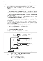
The first phase overcurrent threshold [I>/tI>] ([Ie>/tIe>] for the earth) has a reset timer.
The value that is set for this reset timer corresponds to the minimum time during which the
current value needs to be lower than 95% of the phase (or earth) threshold before the
corresponding phase (or earth) time delay is reset.
NOTE:
This rule doesn’t apply when the protection triggers. When the
protection triggers, the time delay tI> (or tIe>) is immediately reset.
The value of this reset timer depends on the type of timer associated with the first phase
(Earth) threshold.
Reset Timer
Type of timer associated
with the first & second
phase (earth) threshold
P120, P121
P122, P123
DMT (see note below)
0 ms
0 ms to 600 s
Rectifier, IDMT IEC or RI
50 ms
Setting range from 0 to 600 s
RXIDG
-
Setting range from 0 to 600 s
IDMT IEEE or CO
50 ms
Setting range from 0 to 600 s
or
Inverse Time
(Choice of 5 IEEE curves)
(*) first and second earth threshold only
2.5.1
Reset timer (
P122 & P123
only)
For the first phase and earth overcurrent stages, MiCOM P122 and P123 have a timer hold
facility "t Reset", which can be set to a definite time value or to an inverse time characteristic
(IEEE/ANSI curves only). This may be useful for some applications, for example when
grading with upstream electromechanical overcurrent relays which have inherent reset time
delays.
This timer hold facility used to reduce the time to clear a fault is also useful in situations
where intermittent faults occur. This may occur for example in a plastic insulated cable. In
this case, the fault energy may provocate the cable insulation to melt and reseal, thereby
extinguishing the fault. This process repeats itself a couple of times giving a succession of
fault current pulses, each one of increasing duration with reducing intervals between the
pulses, until the fault becomes permanent.
When the reset time of the overcurrent relay is minimum the relay will be repeatedly reset
and not be able to trip until the fault becomes permanent. By using the Timer Hold facility,
the relay will integrate the fault current pulses, thereby reducing fault clearance time.
Summary of Contents for MiCom P120
Page 1: ...MiCOM P120 P121 P122 P123 Overcurrent Relays Version 11 Technical Guide P12X EN T A96...
Page 2: ......
Page 4: ...P12x EN T A96 Technical Guide Contents Page 2 2 MiCOM P120 P121 P122 P123 BLANK PAGE...
Page 13: ...Introduction P12x EN IT A96 MiCOM P120 P121 P122 P123 INTRODUCTION...
Page 14: ......
Page 16: ...P12x EN IT A96 Introduction Page 2 8 MiCOM P120 P121 P122 P123 BLANK PAGE...
Page 22: ...P12x EN IT A96 Introduction Page 8 8 MiCOM P120 P121 P122 P123 BLANK PAGE...
Page 24: ......
Page 35: ...User Guide P12x EN FT A96 MiCOM P120 P121 P122 P123 USER GUIDE...
Page 36: ......
Page 40: ...P12x EN FT A96 User Guide Page 4 72 MiCOM P120 P121 P122 P123 BLANK PAGE...
Page 108: ...P12x EN FT A96 User Guide Page 72 72 MiCOM P120 P121 P122 P123 BLANK PAGE...
Page 109: ...Menu Content Tables P12x EN HI A96 MiCOM P120 P121 P122 P123 MENU CONTENT TABLES...
Page 110: ......
Page 112: ...P12x EN HI A96 Menu Content Tables Page 2 68 MiCOM P120 P121 P122 P123 BLANK PAGE...
Page 180: ......
Page 221: ...Application Guide P12x EN AP A96 MiCOM P120 P121 P122 P123 APPLICATION GUIDE...
Page 222: ......
Page 226: ...P12x EN AP A96 Application Guide Page 4 80 MiCOM P120 P121 P122 P123 BLANK PAGE...
Page 302: ...P12x EN AP A96 Application Guide Page 80 80 MiCOM P120 P121 P122 P123 BLANK PAGE...
Page 304: ......
Page 306: ......
Page 368: ......
Page 370: ...P12x EN CT A96 Communications COURIER DATABASE Page 2 248 MiCOM P120 P121 P122 P123 BLANK PAGE...
Page 514: ...P12x EN CT A96 Communications COURIER DATABASE Page 146 248 MiCOM P120 P121 P122 P123...
Page 516: ......
Page 518: ...P12x EN CT A96 Communications IIEC 60870 5 103 Page 2 248 MiCOM P120 P121 P122 P123 BLANK PAGE...
Page 536: ...P12x EN CT A96 Communications IEC 60870 5 103 Page 20 248 MiCOM P120 P121 P122 P123...
Page 538: ......
Page 540: ...P12x EN CT A96 Communications DNP 3 0 Database Page 2 248 MiCOM P120 P121 P122 P123 BLANK PAGE...
Page 554: ......
Page 573: ...Connection Diagrams P12x EN CO A96 MiCOM P120 P121 P122 P123 CONNECTION DIAGRAMS...
Page 574: ......
Page 580: ......
Page 582: ...P12x EN RS A96 Commissioning Test Record Sheets Page 2 60 MiCOM P120 P121 P122 P123 BLANK PAGE...
Page 642: ......
Page 667: ......