


3-20
CC020D
CF057A
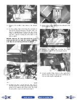
8. Install the four cylinder head cap screws. Tighten
only until snug.
CC272D
9. Loosely install the five cylinder head nuts.
10. In a crisscross pattern, tighten the four cylinder
head cap screws (from step 8) to 40 ft-lb; then
tighten the 8 mm nut (from step 9) to 18 ft-lb.
Using a crisscross pattern, tighten the 6 mm nuts
(from step 9) to 8 ft-lb. Tighten the two cylin-
der-to-crankcase nuts (from step 4) securely.
11. With the timing inspection plug removed and the
chain held tight, rotate the crankshaft until the pis-
ton is at top-dead-center.
12. With the alignment pin installed in the camshaft,
loosely place the cam sprocket (with the recessed
side facing the cam shaft lobes) onto the camshaft.
At this point, do not “seat” the sprocket onto the
shaft.
732-307B
NOTE: At this point, oil the camshaft journals,
cam lobes, and the three seating surfaces on the
cylinder.
13. While holding the cam chain sprocket to the side,
install the rear cam chain tensioner guide into the
cylinder head. Install the pivot cap screw and
washer.
CD461
14. With the cam lobes directed down (toward the pis-
ton), maneuver the camshaft/sprocket assembly
through the chain and towards its seating position;
then loop the chain over the sprocket.
NOTE: Note the position of the alignment marks
on the end of the camshaft. They must be parallel
with the valve cover mating surface. If rotating the
camshaft is necessary for alignment, do not allow
the chain and sprocket to rotate and be sure the
cam lobes end up in the down position.
CD463
Back to TOC
Back to Section TOC
Next
Back