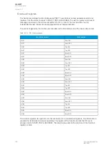
Event block name
Event names
UV4
Block ON
UV4
Block OFF
UV4
Undervoltage Block ON
UV4
Undervoltage Block OFF
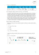
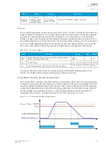
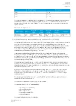
The function registers its operation into the last twelve (12) time-stamped registers; this information is
available for all provided instances separately. The register of the function records the ON event
process data for START, TRIP or BLOCKED. The table below presents the structure of the function's
register content.
Table. 5.4.11 - 122. Register content.
Date and time
Event
Fault
type
Pre-trigger
voltage
Fault
voltage
Pre-fault
voltage
Trip time
remaining
Used SG
dd.mm.yyyy
hh:mm:ss.mss
Event
name
A…A-
B-C
Start/Trip -20ms
voltage
Start/Trip
voltage
Start -200ms
voltage
0 ms...1800s
Setting
group 1...8
active
5.4.12 Neutral overvoltage protection (U0>; 59N)
The neutral overvoltage function is used for non-directional instant and time-delayed earth fault
protection. Each device with a voltage protection module has four (4) available stages of the
function (U0>, U0>>, U0>>>, U0>>>>). The function constantly measures phase-to-earth voltage
magnitudes and calculates the zero sequence component. Neutral overvoltage protection is scaled
to line-to-line RMS level. When the line-to-line voltage of a system is 100 V in the secondary side, the
earth fault is 100 % of the
U
n
and the calculated zero sequence voltage reaches 100/
√
3 V = 57.74 V.
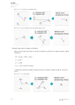
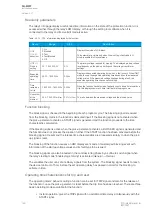
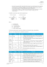
Below is the formula for symmetric component calculation (and therefore to zero sequence voltage
calculation).
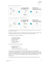
Below are some examples of zero sequence calculation.
Figure. 5.4.12 - 74. Normal situation.
A
AQ
Q-M257
-M257
Instruction manual
Version: 2.07
148
© Arcteq Relays Ltd
IM00021
Summary of Contents for AQ-M257
Page 1: ...AQ M257 Motor protection IED Instruction manual...
Page 2: ......


