


Service Support Spirit
Unique Solution
WWW.ARCBRO.COM
7
Chapter 2 Operation Interface
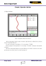
2.1 Main Interface
F1 ShapeLib
F2 Files
F3
PartOption
F4 Setups F5 Diagnose F6 ZoomIn
F7
ManualMove
F8 Zero
FLSK F7500X
Version
7.3.73.1AD
Speed:
00000
File:
SHAPE_43.TXT
Status:
Stop
Current Line/Hole:
00000/00000
+X:500.00 -X:0.00 +Y:500.00 -Y:0.00
1:
(
TEST PATTERN
)
2
:
G92
X
:
+000000.0
Y
:
+000000.0
●
Scavenge 0000.0 s
●
Laser brake 0000.0 s
●
TorchUp 0000.0 s
●
TorchDn 0000.0 s
●
Follow-up 0000.0 s
Manual
【
F
】
StepMov
StepDis
【
G
】
5.00 Flame Cu
【
M
】
CutSpeed
【
X
】
1000.000 Kerf 1.200
ManualSpd
【
Y
】
3000.000 Angle 00.00
①
②
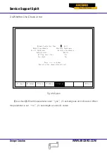
Fig 2.1 Tube/plate cutting main Interface
After use tube/plate cutting module, controller’s main interface is different from common
version. The primary items are:
The end of controller’s model adds a “X”, for an example: “F7500X”.
Add the display of cutting diameter, for an example: “D:160.00”. It interprets that diameter
is 160 mm.
But in the cutting plate interface, except the difference of controller model, the other items
are the same to common model. It is shown as figure 2.2:


