Chapter 9
Relay Contacts and Event Inputs
9.1
Relay Contacts – Option 93
9.1.1
Introduction
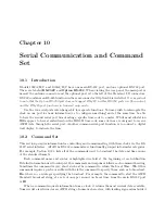
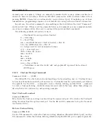
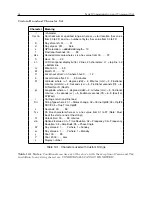
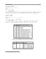
Option 93 provides a single set of SPDT relay contacts when installed the Model 1092A/B/C or
1093A/B/C. Without Option 93 installed, the relay contact connector will be visible, however no
contacts or related circuitry will be installed. To retrofit the Option 93, Out-of-Lock relay, you
must arrange to return it to the factory for installation. These Form C type contacts have a limited
lifetime of approximately 100,000 cycles. See also Section 2.3.5.
9.1.2
Relay Operation
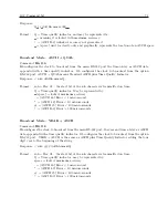
The out-of-lock relay is in the faulted position when the clock is powered OFF (Failsafe operation)
or is not locked to the GPS. The faulted indication is as follows; ERR (Normally Closed) is shorted
to COM and OK (Normally Open) is open with respect to COM. If the clock loses synchronization
with the GPS, the out-of-lock relay will change state (is faulted) based on the “Out-of-Lock” setup.
Configure this through the front panel (see Section 7.5) or the RS-232 interface (see Section 10.2.14).
Out-of-Lock settings are (1) Unlock OFF, (2) Zero Delay Unlock, and (3) 1 to 99 Minute Delay for
unlock.
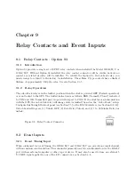
Figure 9.1: Relay Contact Connector
9.2
Event Inputs
9.2.1
Event Timing Input
When configured for event timing, the 1092A/B/C and 1093A/B/C can provide one input channel
with one microsecond resolution. This channel is primarily used for synchronization via the RS-232
port with an external computer or other type of device. It may also be used to time an external 5
V CMOS signal applied to one of the I/O connectors; see Section 5.3.4.
Summary of Contents for 1092A
Page 4: ...iv ...
Page 18: ...xviii LIST OF TABLES ...
Page 129: ...C 10 Option 20A Four Fiber Optic Outputs 111 Figure C 7 Option 20A Jumper Locations ...
Page 131: ...C 11 Option 27 8 Channel High Drive 113 Figure C 8 Option 27 Jumper Locations ...
Page 148: ...130 Options List Figure C 10 Option 29 Connector Signal Locations ...

