Chapter 7
The Setup Menus
7.1
To Begin Configuring
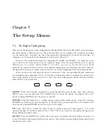
This section should guide you in configuring the Model 1092A/B/C and 1093A/B/C operation using
the setup menus or RS-232 port(s). These menus allow you to configure the operation according
to your preferences. Logically, use the setup menus after installing the clock for the first time, or
changing any of the main board jumpers as described in Chapter 5.
There are two available methods for configuring the 1092B and 1093B/C: (1) Using the lower
row of keys on the front panel, and (2) remotely, using either the main RS-232 port or option
RS-232 port.
To configure Models 1092A/C and 1093A, you must use the RS-232 port(s)
. Both
methods are described in this section. For complete information on configuring all clocks remotely
through either serial port, please refer to Chapter 10, Serial Communication and Command Set.
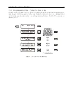
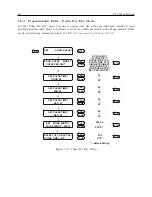
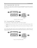
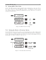
At the end of each setup menu section are references to the corresponding RS-232 commands
for configuring these functions. Table 7.1 lists the various menus used to configure the operation of
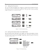
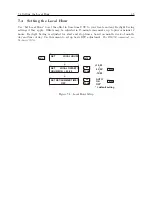
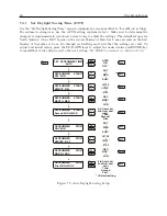
these clock models. Press the setup key to enter the clock configuration menus, starting with the
main RS-232 port parameters.
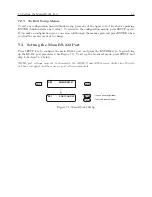
SETUP
DOWN
UP
ENTER
SETUP
: Press the setup key repeatedly to scroll through the main menus. Also, after pressing
SETUP once, you can press the UP or DOWN keys to scroll the menus. In numeric data entry
mode, pressing SETUP moves the cursor to the left.
ENTER
: Press the Enter key to confirm changes made within setup menus. Generally, pressing
ENTER also advances the next parameter, or returns to the previous menu level. In numeric data
entry mode, pressing ENTER moves the cursor to the right.
UP
: Press the UP key, within the setup menus, to adjust numerical values upward, or to scroll
upward through the available menu choices. The UP key also assists in navigating through main
Setup Menus in normal order.
DOWN
: Press the DOWN key, within the setup menu, to adjust numerical values downward, or
to scroll downward through available menu choices. Also assists in navigating through main Setup
menus in reverse order.
Summary of Contents for 1092A
Page 4: ...iv ...
Page 18: ...xviii LIST OF TABLES ...
Page 129: ...C 10 Option 20A Four Fiber Optic Outputs 111 Figure C 7 Option 20A Jumper Locations ...
Page 131: ...C 11 Option 27 8 Channel High Drive 113 Figure C 8 Option 27 Jumper Locations ...
Page 148: ...130 Options List Figure C 10 Option 29 Connector Signal Locations ...

