184
Options List
J2
J3
J4
J5
JMP9
JMP10
JMP11
JMP12
JMP13
JMP14
1
2
3
4
5
6
7
8
9
10
11
12
13
14
15
16
17
18
19
20
21
22
1
2
3
4
5
6
7
8
9
10
11
12
13
14
15
16
17
18
19
20
21
22
1
2
3
4
5
6
7
8
9
10
11
12
13
14
15
16
17
18
19
20
21
22
1
2
3
4
5
6
7
8
9
10
11
12
13
14
15
16
17
18
19
20
21
22
JMP1
JMP2
JMP3
JMP4
J1
Arbiter Systems, Inc.
Assembly Number LB0050300 Rev
.__
A
B
A
B
A
B
A
B
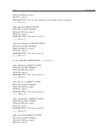
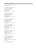
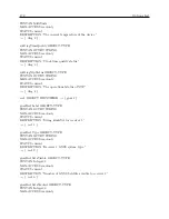
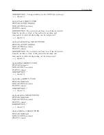
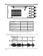
Figure C.43: Option 36 Jumper Configuration
Output Signal
Function Jumper
Mode Jumper
IRIG-B Modulated
1
B
IRIG-B Unmodulated
3
A
1 PPS
18
A
Programmable Pulse
19
A
Out of Lock
20
A
Table C.11: Option 36 Output Connector Jumper Settings
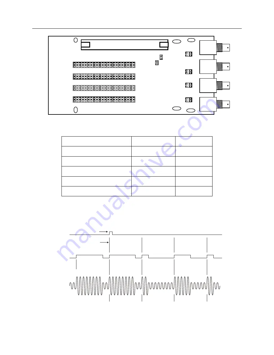
If IRIG-B is chosen as the output signal, then each selected output should produce a waveform
very similar to the drawings in the figure below.
ON-TIME 1 PPS
IRIG
B003
B004
REFERENCE
REFERENCE
IRIG ZERO
IRIG
B123
B124
IRIG ONE
Start of next
second in
time code
MODULATED
UNMODULATED
NOTE: If any of the jumpers were changed, replace the cover to the chassis before returning to
service.
Summary of Contents for 1092A
Page 4: ...iv ...
Page 18: ...xviii LIST OF TABLES ...
Page 129: ...C 10 Option 20A Four Fiber Optic Outputs 111 Figure C 7 Option 20A Jumper Locations ...
Page 131: ...C 11 Option 27 8 Channel High Drive 113 Figure C 8 Option 27 Jumper Locations ...
Page 148: ...130 Options List Figure C 10 Option 29 Connector Signal Locations ...

