B.3 Installation
95
B.3
Installation
B.3.1
Mounting Location
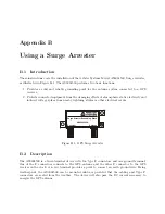
Location is a key consideration when installing the Model AS0094500. Mount as close as possible
to a good earth ground, such as a grounding rod or station ground grid. The shorter the path
between the arrester and the earth ground, the more effectively and reliably it will bypass the
induced voltages.
B.3.2
Ground Connection
The Model AS0094500 can be grounded in two ways: (1) via the ground-wire screw connection, or
(2) by hard-mounting directly to a grounded metal surface.
If grounding via the ground-wire screw connection, use the largest possible gauge wire, with
the shortest possible ground path. Hole diameter allows up to 8 AWG wire (0.129 in or 3.26 mm).
This wire should be as short as possible, and connected to a good earth ground.
Alternately, the AS0094500 could be mounted directly to a well-grounded plate within the
facility.
B.3.3
Antenna and Clock Connections
The AS0094500 is labeled to indicate which terminals should be connected to the GPS receiver and
to the GPS antenna. Use only a low-loss, tri-shield or quad-shield 75-ohm coaxial cable – RG-6
or RG-11 are the preferred cable types. RG-59, or other similar types of coaxial cable, should be
avoided due to greater signal loss and poorer shielding at the GPS frequency (1.575 GHz).
B.3.4
Weather Sealing the Connections
To protect from weather, use only type F connectors with appropriate sealing features. Typically
this includes an o-ring in the male connector that seats against the face of the female connector on
the surge arrester. Also, crimped connectors frequently include a silicone gel flooding compound,
which enhances the ability of the connection to withstand the rain and humid conditions. To better
seal the entire connection, cover the joint with GE Silicone II compound.
Use the proper crimping tool if using crimp-on connectors. Improper tools may not guarantee a
strong and sufficiently grounded connector resulting in poor cable performance and GPS reception.
Consider purchasing RF cables of various standard and custom lengths manufactured by Arbiter
Systems.
B.3.5
Suggested Mounting
Figure B.2 illustrates the recommended mounting of the AS0094500 with the F-connectors facing
downward. Install drip loops in the cables to reduce the likelihood of moisture penetrating the
device.
Summary of Contents for 1092A
Page 4: ...iv ...
Page 18: ...xviii LIST OF TABLES ...
Page 129: ...C 10 Option 20A Four Fiber Optic Outputs 111 Figure C 7 Option 20A Jumper Locations ...
Page 131: ...C 11 Option 27 8 Channel High Drive 113 Figure C 8 Option 27 Jumper Locations ...
Page 148: ...130 Options List Figure C 10 Option 29 Connector Signal Locations ...

