9.2 Command Set
75
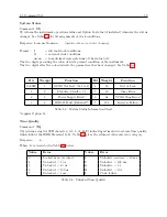
Broadcast Mode - NMEA183ZDA
Command:
1,nB
1,nB configures the clock to broadcast the National Marine Electronics Association Standard
(NMEA - 0183) to broadcast ZDA format from the main RS-232C port, where n = the update rate
in seconds from 1 to 9999. ZDA, time and date, includes the UTC day, month, year, and local time
zone.
Response:
$–ZDA,hhmmss.ss,dd,mm,yyyy,xx,xx
C
Where:
ZDA
Time and date
hhmmss.ss
Time in UTC
dd
Day, 01 to 31
mm
Month, 01 to 12
yyyy
Year
xx.xx
Local zone description, 00 to +/- 13 hours and minutes
9.2.2
Event Mode Commands
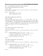
Return Specific Event
Command:
nnnA, nnnB
nnnA sets the event buffer read index to a specific event number (0 to 199) for channel A, and nnnB
sets the event buffer read index to a specific event number (0 to 199) for channel B. It then returns
that event information in either Local or UTC time format depending on how the command, nTA
or nTB is configured.
Response:
LCL mm/dd/yyyy hh:mm:ss.sssssss nnnAL (or ...BL)
C
or
UTC mm/dd/yyyy hh:mm:ss.sssssss nnnAU (or ...BU)
C
Format:
nnn
Event–Buffer Read Index Number
A
Channel A
B
Channel B
U
UTC Time, Channel A or B.
L
Local Time, channel A or B.
Set Event Channel Time
Command:
nTA, nTB
nTA sets the channel A time source, and nTB sets the channel B time source, as either Local or
UTC, where n = 0 sets the event time to UTC and n = 1 sets the event time to Local.
Response:
C
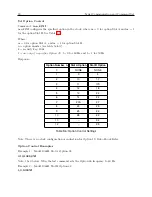
Set Channel – Deviation
Command:
AD, BD
AD sets channel A, and BD sets channel B, to the 1-PPS deviation mode.
Response:
C
Summary of Contents for 1088A
Page 4: ...iv ...
Page 6: ...vi ...
Page 18: ...xviii LIST OF FIGURES ...
Page 23: ...1 4 Attaching Rack Mount Ears to 1088A B Series Clocks 3 Figure 1 2 Attaching Rack Mount Ears ...
Page 24: ...4 Unpacking the Clock ...
Page 32: ...12 Front and Rear Panels ...
Page 38: ...18 Connecting Inlet Power Input and Output Signals ...
Page 46: ...26 GPS Antenna and Cable Information ...
Page 48: ...28 Setting Internal Jumpers Figure 5 1 Model 1088B Main Board ...
Page 76: ...56 The Setup Menus ...
Page 112: ...92 Serial Communication and Command Set ...
Page 127: ...B 4 Physical Dimensions 107 Figure B 1 Suggested Mounting of the AS0094500 Surge Arrester ...
Page 128: ...108 Using Surge Arresters ...
Page 145: ...C 5 Option 04 Parallel BCD Output 125 Figure C 4 Option 04 Output Jumper Settings ...
Page 146: ...126 Options List Figure C 5 Option 04 Board Layout and Jumper Locations ...
Page 166: ...146 Options List Figure C 12 Option 17 Board Layout and Jumper Locations ...
Page 187: ...C 16 Option 20A Four Fiber Optic Outputs 167 Figure C 22 Option 20A Jumper Locations ...
Page 194: ...174 Options List Figure C 24 Option 23 Internal Jumper Setup ...
Page 196: ...176 Options List Figure C 25 Option 27 Jumper Locations ...
Page 214: ...194 Options List Figure C 28 Option 29 Connector Signal Locations ...
Page 270: ...250 Options List ...


