182
Options List
C.19.6
Phase Calibration
The factory performs phase calibration, and supplies the calibration factor with the assembly. To
be effective, it must be entered into the clock non-volatile memory. Entering this factor into the
clock requires connecting the clock to a computer or terminal via the RS-232 interface (see clock
manual). For the computer, use a terminal-emulation program such as Procomm or Windows
Terminal. Send the character “V” to the clock to check that connections and port settings are
correct. The clock should respond with the firmware dates in the format “01 Jan 1997 Op28 02
Jan 1997.”
To send the phase calibration factor to the clock, key in the message:
dd.dd,1088PC
Where dd.dd is the calibration factor in degrees, for example “-0.16”; and 1088 is the clock model
number (a security key to prevent unintentional modification):
-0.16,1088PC
C.19.7
Amplitude Calibration
For amplitude calibration, the format is similar, replacing “PC” with “RV”. The calibration factor
(supplied with boards having a serial number with prefix greater than 97420) is approximately
1.0, and is multiplied by the measured result to generate the displayed value. If an accurate ac
source at 50 or 60 Hz is available (for example, the Arbiter Systems, Inc. Model 1040C Panel
Meter Calibrator), the error (for boards with prefix 97420) can be measured and the correction
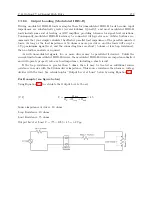
factor entered as described. For example, if applying 120 Vrms to the Option 28 assembly, and
the display indicates 119.1 Vrms, the calibration factor is (120.0 / 119.1) or 1.0076. You would
enter “1.0076,1088RV” to calibrate the unit (model 1088A/B). The display should then read close
to 120.0 Vrms. To clear the calibration factor, you may set the unit to factory defaults or send the
command “1,1088RV.”
Summary of Contents for 1088A
Page 4: ...iv ...
Page 6: ...vi ...
Page 18: ...xviii LIST OF FIGURES ...
Page 23: ...1 4 Attaching Rack Mount Ears to 1088A B Series Clocks 3 Figure 1 2 Attaching Rack Mount Ears ...
Page 24: ...4 Unpacking the Clock ...
Page 32: ...12 Front and Rear Panels ...
Page 38: ...18 Connecting Inlet Power Input and Output Signals ...
Page 46: ...26 GPS Antenna and Cable Information ...
Page 48: ...28 Setting Internal Jumpers Figure 5 1 Model 1088B Main Board ...
Page 76: ...56 The Setup Menus ...
Page 112: ...92 Serial Communication and Command Set ...
Page 127: ...B 4 Physical Dimensions 107 Figure B 1 Suggested Mounting of the AS0094500 Surge Arrester ...
Page 128: ...108 Using Surge Arresters ...
Page 145: ...C 5 Option 04 Parallel BCD Output 125 Figure C 4 Option 04 Output Jumper Settings ...
Page 146: ...126 Options List Figure C 5 Option 04 Board Layout and Jumper Locations ...
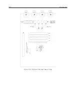
Page 166: ...146 Options List Figure C 12 Option 17 Board Layout and Jumper Locations ...
Page 187: ...C 16 Option 20A Four Fiber Optic Outputs 167 Figure C 22 Option 20A Jumper Locations ...
Page 194: ...174 Options List Figure C 24 Option 23 Internal Jumper Setup ...
Page 196: ...176 Options List Figure C 25 Option 27 Jumper Locations ...
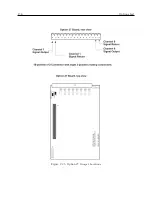
Page 214: ...194 Options List Figure C 28 Option 29 Connector Signal Locations ...
Page 270: ...250 Options List ...


